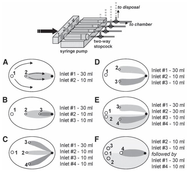
Fig. 2.
Modifications of the local injury chamber. A variety of flow patterns can be obtained by changing inlet positions and syringes size. Inlets are shown as open circles and marked by the numbers. Corresponding syringe sizes for the depicted patterns are shown on the right. The outlet opening is shown as a black circle. (A) Single injury zone chamber. Arrows show the direction of the flow within the two zones. The injury zone (I-zone) is shown in gray and the control zone (C-zone) is shown in white. (B) Nested injury chamber that creates three distinct environments, including two injury zones. (C) Trefoil chamber that creates one C-zone and three small I- zones. (D) Double injury chamber. (E) Double injury chamber with split C-zone. This design allows side-by-side comparison of two reperfusion protocols. (F) Double staining chamber. It allows staining of a cell coverslip with two different dyes (shaded areas). The extracellular dyes are then washed out with the control solution (inlet 1), which is followed by an application of the injury solution via inlet 4. The I-zone (shown in gray) is then created over the two areas of cell network stained with different fluorescent indicators.

