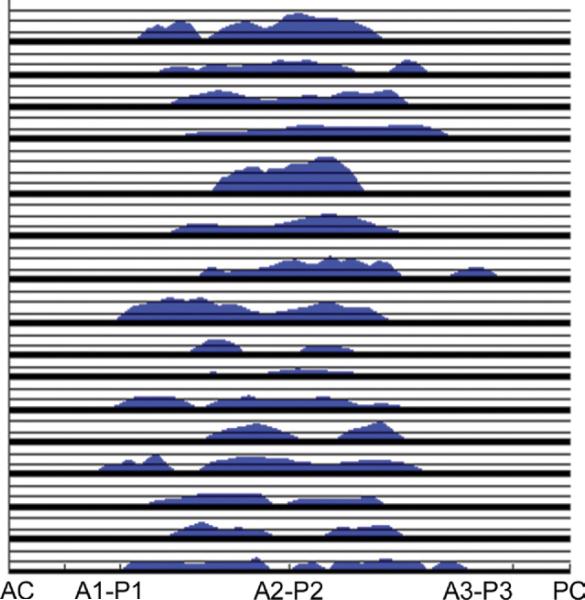
Fig 7.
Regurgitant orifice geometry, presented as orifice width plotted as a function of location along coaptation line (expressed as a percentage of the distance traveled from the anterior commissure). The positions of the anterior commissure (AC) and posterior commissure (PC) and valve segments (A1-P1 to A3-P3) are labeled. To avoid curves overlapping, all patients have been overlaid. Each vertical graduation represents 1-mm regurgitant width. Note extension of regurgitant orifice along the entire coaptation region and also the variable size and number of orifices.

