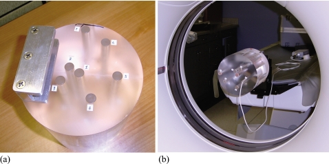
Figure 2.
(a) Custom-designed CT dose phantom for measuring center-to-periphery dose distributions. The locations of the seven drill holes are numbered. (b) Measurements of dose distribution in the custom-designed phantom. The phantom was attached to one end of the CT table and positioned so that its long axis matched the axis of gantry rotation.

