
Fig. 4.
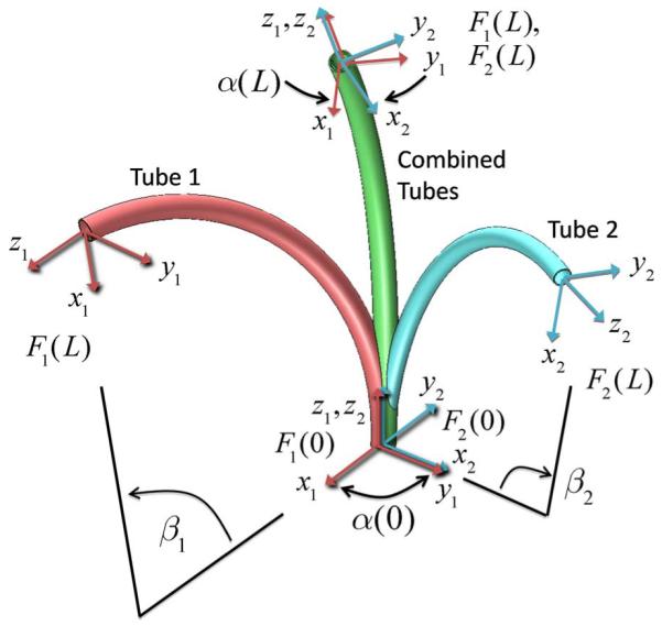
Effect of torsional twisting when two curved tubes are combined. Tube coordinate frames are denoted by Fi(s). The relative z-axis twist angle between frames α(s) varies from a maximum α(0) at the base to a minimum α(L) at the tip. The central angles βi are proportional to the precurvature and to the tube length L.