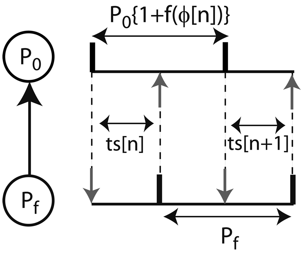
FIGURE 3.
A periodically forced oscillator. Stimulus intervals (ts) in the nth and (n+1)st cycles in a phase locked mode with no delays is shown here. The black vertical bars indicate firing times and the vertical gray arrows indicate neuronal inputs arriving at a phase ϕ (= ts / P0). P0 represents the period of the forced oscillator and Pf represents the period of the forcing oscillator.

