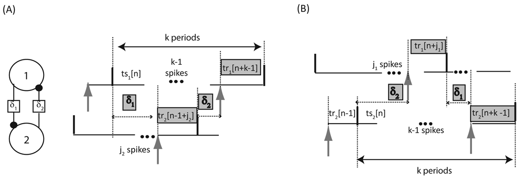
FIGURE 7.
Neural firing time map with delays of arbitrary lengths for a circuit of two pulse coupled neurons. Only two out of the four possible firing patterns are shown. The delay between a spike in neuron 1 (2) and the receipt of an input by neuron 2 (1) is designated δ1 (δ2). The delay between a spike in neuron 1 (2) and the receipt of an input by neuron 2 (1) is designated δ1 (δ2). (A) The quantities highlighted in gray sum to k cycles in neuron 1. The number of spikes that occur in neuron 2 during δ1 is j2. (B) The quantities highlighted in gray sum to k cycles in neuron 2. The number of spikes that occur in neuron 1 during δ2 is j1. Stimulus intervals (tsi) denote the time elapsed between a spike in neuron i and the receipt of the next input by neuron i, whereas recovery intervals (tri) denote the time elapsed between the receipt of an input by neuron i and the next spike in neuron i. The time intervals are variable and indexed by cycle number n.

