Abstract
A size-selective cell sorting microfluidic device that utilizes optical force is developed. The device consists of a three-dimensional polydimethylsiloxane microstructure comprised of two crossed microchannels in a three-dimensional configuration. A line shaped focused laser beam is used for automatic size-selective cell sorting in a continuous flow environment. As yeast cells in an aqueous medium are fed continuously into a lower channel, the line shaped focused laser beam is applied (perpendicular to the direction of flow) at the junction of the two crossed channels. The scattering force of the laser beam was employed to push cells matching specific criteria upward from one channel to another. The force depends on the size of the cells, the laser power, and the fluid flow speed. The variation in size of yeast cells causes them to follow different routes at the intersection. For flow speeds below 30 μm∕s, all yeast cells larger than 3 μm were removed from the main stream. As a result, a high purity sample of small cells can be collected at the outlet of bottom channel.
INTRODUCTION
Conventional cytometry systems are becoming mature tools for rapid and reliable cell counting, sorting, and analysis. However, complicated operating units and delicate optical components such as detection∕filtering devices make systems bulky and expensive. Furthermore, specialists are typically required to operate flow cytometers due to the complicated sample pretreatment procedures involved. In recent years, advancement in microfabrication technologies has allowed for the development of miniaturized flow cytometers.1 Miniaturized flow cytometers are particularly appealing for cell separation because of the dramatic reduction in the amount of sample required. The ability to extract rare cells from a larger mixed population for further processing is essential for life science research and diagnostic platforms. This is particularly important if one is using precious cells that cannot be easily expanded into large populations, for example, stem cells or metastatic cancer cells. Several research groups have demonstrated innovative sorting techniques that show promise for sorting live cells in microfluidic devices, each with its own merits and drawbacks.2, 3, 4, 5, 6, 7, 8, 9 Among these techniques, the electric field-based separation approach utilizing dielectrophoretic force5, 6, 7, 8, 9 has proved to be an effective and appealing tool for cell sorting by many researchers. This is because the fluid flow inside the microchannel can be easily controlled by electric field resulting in a high degree of sorting accuracy. However, the complex fabrication of the microelectrodes and the inherent drawbacks such as viability of cells, buffer incompatibility, and the frequent need to finely tune the voltage setting whenever conditions change limit the application of the electric field-based separation approach.
Recently, microfluidic sorting using optical force has proved to be an attractive option due to the noninvasive and sterile nature of the optical force.10 In contrast to electric field-based methods, the optical force acts on biological cells with minimum degradation. Optical separation of cells has previously been shown without the inclusion of fluid flow.11 Paterson et al.12, 13 has demonstrated the use of optical force for sorting a mixed sample of lymphocytes and erythrocytes cells in the absence of externally driven fluid flow. The main drawback of flow free techniques is that cells cannot be separated continuously into different fluidic channels. Recently, breakthroughs were made by Wang et al.14 and Perroud et al.15 who reported the use of a fully optical control switch for continuous sorting of live cells. Both devices were based on a fluorescence triggered scheme and optical force to deflect cells into the desired output channel automatically. Fluorescence-activated cell sorting (FACS) requires fluorescent markers or antibodies to attach to the cells of interest. Fluorescent labeling of cells is time consuming and is dependent on the availability of appropriate antibodies that tag onto the target cell surface. Hence, several research groups are beginning to probe the potential of passive optical sorting techniques which obviate the need to add any dielectric tags or surface markers.10, 16, 17, 18
The effectiveness of sorting colloidal particles using optical force based on their intrinsic properties such as refractive index and size has been demonstrated.15, 16, 19, 20, 21, 22, 23 However, passively sorting native (unlabeled) cells using optical force has not been well exploited in a continuous flow environment. This is primarily due to the fact that the refractive index difference between different viable cells is typically small. This means that the optical force is not sensitive enough to exert significantly different optical forces to separate them. This has prompted researchers to separate cell mixtures according to size difference instead. However, optical force can only separate cells if they differ substantially in size. For example, Paterson et al.13 failed to separate the HL60 cell line according to their size difference with diameter vary from 9 to 13 μm.
In this paper, we propose a technique that takes advantage of a mildly focused lined laser coupled to a three-dimensional PDMS cross-microchannel to enable passive and continuous separation of cells. As a difference from other optical sorting techniques, we attempted to solve a few limitations that have hindered optical sorting for practical use in this work. Living cells are used as sample components instead of microspheres such as polystyrene and silica beads. Continuous separation with a relatively fast response time is made possible. Sorting multiple cells at the same time without the need for hydrodynamic focusing of cell stream is an added advantage. Furthermore, in combination with microfluidic channels, sorted cells are readily collected in the collection outlet.
The laser beam that spans across the intersection of the channel provides an optical force orthogonal to the direction of fluid flow at the intersection. This is desirable as cells of different sizes can be continuously separated and flowed into separate fluid channels downstream in the chip. To facilitate this study, we used yeast cells to serve as our model biological cells. Yeast cells vary in size because they are at different stages of the cell cycle. In this work, we have utilized the native properties of the cells—their difference in size to demonstrate that extraction of smaller cells is feasible, even though their size difference is less than 5 μm. Our method is particularly appealing when the target cells are smaller cells in the population. On the other hand, we may use this method to purify the cell mixture by removing the lysis debris or large cells cluster. As one of the major advantages, separating∕removing target cells of a different size does not require a new channel configuration or modified dimensions. The only adjustment is to carefully control the flow rate or laser power.
Our optical sorting method allows multiple cells to be manipulated at the same time without the need for an active recognition step. The switching is mainly based on the optical scattering force of a focused laser beam and the use of a low numerical aperture (NA) objective lens. Simultaneous sorting of multiple cells was made possible with the lined shape laser beam created when the laser passed through a cylindrical lens. Particle sorting takes place in a relatively small “sorting box” formed by the intersection of two cross channels, thus eliminating the need for long channels or large fractionating arrays.
EXPERIMENTAL
Fabrication of microfluidic chips
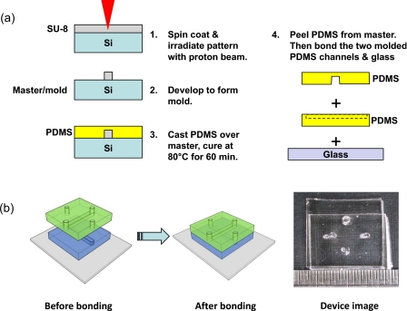
A schematic of the device fabrication steps is shown in Fig. 1. In order to utilize optical trapping and manipulation for sorting in a microfluidic system, a device needs to be fabricated in a material that is transparent to the laser beam used for manipulation. The material chosen for our device was polydimethylsiloxane (PDMS). PDMS is a low cost silicon-based organic polymer that is routinely used in the fabrication of lab-on-a-chip devices by soft lithography. To construct the sorting device, first a master mold was fabricated in a layer of SU-8 photoresist spin coated onto a silicon wafer by using the proton beam writing technique.24 After development of the SU-8 structure, a hard bake was performed to create a permanent, reusable master that could be used for soft lithography. PDMS molding was carried out to obtain the inverse structures of the master mold. Holes were then punched at the inlets of the device using a Harris Uni-Core punch and the PDMS was trimmed to size. In order to make the final microfluidic device, two pieces of PDMS containing the microchannels were first cleaned using ethanol under sonication and then exposed to air plasma (plasma cleaner, Harrick Plasma) for 10 s. The two PDMS channels were then bonded to each other such that the two microchannels formed a “tangential contact.” Finally, the samples were bonded to a piece of glass slide and heated in an oven at 80 °C for 60 min.
Figure 1.
(a) Processing steps for fabricating the PDMS microchannels and the two level sorting device. (b) The bonding procedure for the final device.
Experimental procedures
Cell separation with the optical device was performed using baker’s yeast (saccharomyces cerevisiae). Yeast is diluted in purified water, until a concentration that ensures an acceptable density of cells flowing in the lower channel of the microfluidic device has been obtained. This is done by inspecting a drop of the sample under a microscope. Then, the yeast cells were incubated at 37 °C for a period of 10 h before they were used in the experiments. To characterize the microchannel device, the yeast cells mixture was introduced into the lower channel, while de-ionized water was introduced into the upper channel. There is no hydrodynamic focusing of the cells as required in FACS. The yeast cells typically flowed along the bottom of the channel at low speed due to the density difference between the cells and the surrounding medium. We took advantages of this and focused the laser at the bottom of the lower channel to allow the cells to interact with the line laser that span across the whole sorting box. By not employing complicated two-dimensional or three-dimensional focusing, the operation of the sorting device can be simpler and more effective.
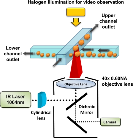
At the channel intersection, the flow pattern strongly depends on the aspect ratio of the microchannels.25 The fluid is driven by a syringe pump (KDS 250) and flows straight through the intersection without any significant exchange of fluid between the channels, provided the aspect ratio is high (e.g., 1.6). As the cells pass by the intersection, they are subjected to a net optical force perpendicular to the direction of flow. Selected cells are strongly pushed upward and switched to the upper channel while the others pass straight through. The difference in the behavior depends on their sensitivity to the optical force. Figure 2 shows the overall concept for a sorting device that switches cells matching specific criteria from the lower channel to the upper channel. Since there is a sustained fluid flow in both the lower and upper channels, when the cells move up, they are carried away by the flow automatically. The simple operation of the device allows for an efficient and automated method of sorting cells without the need to turn off or translate the laser beam. A single spot focused laser beam was initially used in the cell sorting device. However it was slow and inefficient because it was only able to sort cells in the immediate surroundings of the focal point. A larger active sorting area in the cross-channel is achieved by introducing a cylindrical lens into the optical train to spread the beam into a line focus.19 The line shaped focused laser beam was able to cover the whole “sorting box” (50 μm). This modification to the optical system significantly increased the throughput of the sorting process by allowing for the simultaneous manipulation of multiple cells.
Figure 2.
Schematic of optical sorting microfluidic system. The focused laser was applied at the junction of the two overlapping channels.
In order to observe the operation of the cell sorting device, the sorting chip was mounted on an inverted microscope (Nikon TE2000-U). A dichroic mirror was used to reflect the laser beam (DPSS laser, 1064 nm, max 1500 mW) toward the back aperture of the objective lens (40×0.60 NA Nikon) while allowing for the illumination light and particle image to pass through to a charge-coupled device video camera connected to a personal computer. Using this setup, the operation of the device could be observed in real time. The infrared laser power at the back aperture of the objective lens was measured to be 150 mW.
RESULTS AND DISCUSSION
The operation of the microfluidic optical sorting device may be viewed in the video footage provided in the supplementary material. In order to understand its operation one must consider the forces acting on the cells as they move through the intersection of the two channels. The force on a cell in an optical trap is the net result of a scattering force and a gradient force. When cells first encounter the focused laser beam, the gradient force acts to rapidly slow them down. In order for this to occur, the gradient force must be sufficiently large to overcome the drag force. The interplay between the optical gradient force and the fluid drag force determines the sorting criterion. If the velocity of the cells is too high, then for a given laser power and objective lens NA, the optical gradient force is insufficient to stop the cells. In addition to being stopped by the optical gradient force, a scattering force will act on the cell in a direction perpendicular to the fluid flow. The strength of the gradient force and scattering force depends on the size and intensity of input laser.26, 27 Therefore cells that are larger in size are more readily deflected by the optical field. For objective lenses that have a relatively low NA, the scattering force dominates over the gradient force resulting in the particle being pushed by the laser rather than being trapped at the focus. The deflection of some of the cells by the scattering force is the main mechanism for sorting in the microfluidic device. Cells that meet specific criteria primarily determined by their size and the laser power can be separated from a mixture by being pushed by a focused laser into an upper channel.
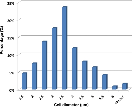
Yeast cells vary in size because they are at different stages of the cell cycle. These cells are used in the optical separation to determine if the variation in size of cells of a single type causes them to follow different routes at the intersection under the optical field. As shown in Fig. 3, the size of the yeast cells was determined optically and it ranged in diameter from 1.5 to 5 μm, with a Gaussian distribution of size, and the average diameter being around 3.4 μm. In order to differentiate the larger cells and smaller cells, we grouped them into two groups, with cells that are smaller than 3 μm in diameter as “small cells,” while those larger than 3 μm in diameter as “large cells.” Before separation, 43.4% of yeast cells are small cells and 56.6% of cells are large cells.
Figure 3.
Size distribution of yeast cells before separation. We grouped these cells into two groups: small cells (diameter <3 μm, 43.4%) and large cells (diameter >3 μm, 56.6%).
To enhance the sorting efficiency, a high aspect ratio microchannel (Aspect Ratio=1.6, width=25 μm, high=40 μm) device was adopted.25 The sorting experiments were repeated using different flow speed under a constant laser power of 150 mW. Since viability of the cells after separation is critical for subsequent analysis, the experiment was not performed using higher power though higher power would give rise to optimum separation at higher velocity. As reported in Paterson et al.,13 cells remained viable after exposure to 500 mW of 1064 nm laser beam for approximately 60 s. In our experiments, the time that cells were exposed to 150 mW of lined laser with the same wavelength was less than 1 s. This is to make sure that the laser beam does no harm to the cell. The yeast cell suspension was continuously introduced into the bottom channel. At optimum flow speed, with optical gradient force is only sufficient to stop the larger cells, cells larger than a specific size were removed from the mainstream. The smaller cells passed straight through the intersection and were collected at outlet of bottom channel. Figure 4 (enhanced) shows sequential images of yeast cell passing through the intersection. Small (white arrows, 1 and 2) and large (yellow arrows, 3, 4 and 5) yeast cells were initially flowing in the bottom channel. When they encounter the line laser (dashed box), the large yeast cell are stopped and pushed to the upper channel while the small yeast cell passed straight through. As a result, the large cells and small cells were successfully separated.
Figure 4.
Sequential images of yeast cell when passing through the intersection. (a) Small (white arrows, 1 and 2) and large (yellow arrows, 3, 4, and 5) yeast cells initially flowing in the bottom channel. (b) When they encounter the line laser (dashed box), the large yeast cell was stopped and pushed to upper channel while the small yeast cell passed straight through. (c) and (d) The cells that are moving to the top channel become out of focus and disappear from the image when it is totally switched to top channel. The large cell and small cell are successfully separated and are readily collected at two different outlets. The sorting box was 25×25×80 μm3 in size. The cells were moving at speeds of ∼30 μm∕s. The blue arrows show the direction of fluid flow (enhanced online). 1
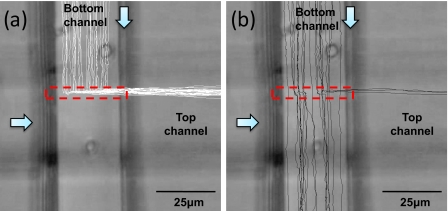
Figures 5a, 5b show the trajectories of large cells with a diameter more than 3 μm (white lines) and small cells with a diameter less than 3 μm (black lines), respectively, in the presence of a line laser (dashed box). Due to the laminar flow of the microfluidic system, the tracks of the separated cells form a band which corresponds to the optical trap line. The particle flow speed was varied from 5 to 90 μm∕s. At optimum flow speed of ∼30 μm∕s, a majority of the smaller cells were not switched by the laser while all large cells were switched efficiently when they encountered the line laser. As a result, the sample comprises of a high purity of small cells and can be collected in outlet of bottom channel.
Figure 5.
(a) Trajectories of large cells (diameter >3 μm) and (b) small cells (diameter <3 μm). The dashed box indicates the line laser and white arrows show the direction of fluid flow. Cells are moving at ∼30 μm∕s.
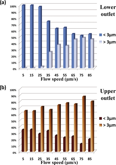
The performance of the sorting system can be illustrated by means of Fig. 6. Quantitative analysis of cells was carried out from a statistical analysis of more than 1000 yeast cells. The velocity and size of the separated cells were measured and these cells were grouped into two groups: small cells (diameter <3 μm) and large cells (diameter >3 μm). By changing the fluid flowing speed using the syringe pump, the cells that go to two different outlets were analyzed to determine the size distribution of the collected cells in both outlets. For all the cells that keep flowing straight in the lower channel, the percentages of small cell and large cell were determined at various velocity. The same analysis was carried out with the cells that were switched to the upper channel. Histograms showing the composition ratio of cells in both outlets at various flow speeds is shown in Fig. 6.
Figure 6.
(a) Composition ratio of cells collected in lower outlet. (b) Composition ratio of cells collected in upper outlet. Cells were grouped into larger and smaller than 3 μm in diameter.
Figure 6a shows the composition ratio of cells that passed straight through the sorting box (lower outlet). Below 30 μm∕s, the optical force was sufficient to stop and push all the large cells to upper channels, which result in over 96% of small cells being collected in lower outlet. The histograms illustrate that, in general, the composition of the large cells is increasing as their velocity increases. We attribute this to the increasing number of large cells that were not switched successfully due to their being an insufficient gradient force to overcome the viscous drag force. Consequently, the composition of the small cells dropped gradually as expected. Optimum separation of the cells (large cells 100% removed from mainstream) can be attained at higher velocity if higher laser power is used.
We can observe that the composition ratio of large cells in upper channel outlet is higher than small cells. This is because large cells experienced a stronger optical force and hence switched more efficiently than small cells. As the velocity increased, large cells start to dominate over the small cells resulting in an 80∕20 population ratio. Using flow a speed beyond 90 μm∕s may cause higher purity of large cells collected but the efficiency and throughput of the sorting is reduced significantly beyond 90 μm∕s.
CONCLUSION
We present here a noninvasive and versatile method for yeast cell separation∕enrichment that combines microfluidic channels and optical force. We have utilized the native properties of the cells, namely, their difference in size to demonstrate that extraction of smaller cells is feasible with optical method. The method is simple and effective and eliminates the problem of sample labeling, contamination, and hydrodynamic focusing. We have performed a statistical analysis of the sorting results at different flow rate. Under certain circumstances, recovery yield over 95% was achieved for yeast cells sample ranging from 1.5 to 5 μm.
ACKNOWLEDGMENTS
Funding support by the Singapore Ministry of Education (MOE)-Academic Research Fund (AcRF) tier 1 grant (Grant No. R-144-000-258-112) is acknowledged.
References
- Chung T. D. and Kim H. C., Electrophoresis 28, 4511 (2007). 10.1002/elps.200700620 [DOI] [PubMed] [Google Scholar]
- Shevkoplyas S. S., Yoshida T., Munn L. L., and Bitensky M. W., Anal. Chem. 77, 933 (2005). 10.1021/ac049037i [DOI] [PMC free article] [PubMed] [Google Scholar]
- Yamada M., Kano K., Tsuda Y., Kobayashi J., Yamato M., Seki M., and Okano T., Biomed. Microdevices 9, 637 (2007). 10.1007/s10544-007-9055-5 [DOI] [PubMed] [Google Scholar]
- Kwon K. W., Choi S. S., Lee S. H., Kim B., Lee S. N., Park M. C., Kim P., Hwang S. Y., and Suh K. Y., Lab Chip 7, 1461 (2007). 10.1039/b710054j [DOI] [PubMed] [Google Scholar]
- Hu X., Bessette P. H., Qian J., Meinhart C. D., Daugherty P. S., and Soh H. T., Proc. Natl. Acad. Sci. U.S.A. 102, 15757 (2005). 10.1073/pnas.0507719102 [DOI] [PMC free article] [PubMed] [Google Scholar]
- Vahey M. D. and Voldman J., Anal. Chem. 80, 3135 (2008). 10.1021/ac7020568 [DOI] [PubMed] [Google Scholar]
- Braschler T., Demierre N., Nascimento E., Silva T., Oliva A. G., and Renaud P., Lab Chip 8, 280 (2008). 10.1039/b710303d [DOI] [PubMed] [Google Scholar]
- Khoshmanesh K., Zhang C., Lopez F. J. T., Nahavandi S., Baratchi S., Mitchell A., and Zadeh K. K., Microfluid. Nanofluid. 9, 411 (2010). 10.1007/s10404-009-0558-7 [DOI] [Google Scholar]
- Khoshmanesh K., Zhang C., Nahavandi S., Lopez F. J. T., Baratchi S., Hu Z., Mitchell A., and Zadeh K. K., Electrophoresis 31, 1366 (2010). 10.1002/elps.200900717 [DOI] [PubMed] [Google Scholar]
- MacDonald M. P., Spalding G. C., and Dholakia K., Nature (London) 426, 421 (2003). 10.1038/nature02144 [DOI] [PubMed] [Google Scholar]
- Jákl P., Cizmar T., Sery M., and Zemanek P., Appl. Phys. Lett. 92, 161110 (2008). 10.1063/1.2913759 [DOI] [Google Scholar]
- Paterson L., Papagiakoumou E., Milne G., Chavez V. G., Tatarkova S. A., Sibbett W., Gunn-Moore F. J., Bryant P. E., Riches A. C., and Dholakia K., Appl. Phys. Lett. 87, 123901 (2005). 10.1063/1.2045548 [DOI] [Google Scholar]
- Paterson L., Papagiakoumou E., Milne G., Chavez V. G., Briscoe T., Sibbett W., Dholakia K., and Riches A. C., J. Biomed. Opt. 12, 054017 (2007). 10.1117/1.2794780 [DOI] [PubMed] [Google Scholar]
- Wang M. M., Tu E., Raymond D. E., Yang J. M., Zhang H., Hagen N., Dees B., Mercer E. M., Forster A. H., Kariv I., Marchand P. J., and Butler W. F., Nat. Biotechnol. 23, 83 (2005). 10.1038/nbt1050 [DOI] [PubMed] [Google Scholar]
- Perroud T. D., Kaiser J. N., Sy J. C., Lane T. W., Branda C. S., Singh A. K., and Patel K. D., Anal. Chem. 80, 6365 (2008). 10.1021/ac8007779 [DOI] [PubMed] [Google Scholar]
- Milne G., Rhodes D., MacDonald M., and Dholakia K., Opt. Lett. 32, 1144 (2007). 10.1364/OL.32.001144 [DOI] [PubMed] [Google Scholar]
- Applegate R. W., Squier J., Vestad T., Oakey J., and Marr D., Opt. Express 12, 4390 (2004). 10.1364/OPEX.12.004390 [DOI] [PubMed] [Google Scholar]
- Hart S. J., Terray A. V., and Arnold J., Appl. Phys. Lett. 91, 171121 (2007). 10.1063/1.2799180 [DOI] [Google Scholar]
- Cheong F. C., Sow C. H., Wee A. T. S., Shao P., Bettiol A. A., Van Kan J. A., and Watt F., Appl. Phys. B: Lasers Opt. 83, 121 (2006). 10.1007/s00340-006-2139-8 [DOI] [Google Scholar]
- Sun Y. Y., Yuan X. C., Ong L. S., Bu J., Zhu S. W., and Liu R., Appl. Phys. Lett. 90, 031107 (2007). 10.1063/1.2431768 [DOI] [Google Scholar]
- Lin C. C., Chen A., and Lin C. H., Biomed. Microdevices 10, 55 (2008). 10.1007/s10544-007-9109-8 [DOI] [PubMed] [Google Scholar]
- Marchington R. F., Mazilu M., Kuriakose S., Chavez V. G., Reece P. J., Krauss T. F., Gu M., and Dholakia K., Opt. Express 16, 3712 (2008). 10.1364/OE.16.003712 [DOI] [PubMed] [Google Scholar]
- Hoi S. K., Udalagama C., Sow C. H., Watt F., and Bettiol A. A., Appl. Phys. B: Lasers Opt. 97, 859 (2009). 10.1007/s00340-009-3687-5 [DOI] [Google Scholar]
- van Kan J. A., Wang L. P., Shao P. G., Bettiol A. A., and Watt F., Nucl. Instrum. Methods Phys. Res. B 260, 353 (2007). 10.1016/j.nimb.2007.02.046 [DOI] [Google Scholar]
- Ismagilov R. F., Rosmarin D., Kenis P. J. A., Chiu D. T., Zhang W., Stone H. A., and Whitesides G. M., Anal. Chem. 73, 4682 (2001). 10.1021/ac010374q [DOI] [PubMed] [Google Scholar]
- Ashkin A., Appl. Phys. Lett. 19, 283 (1971). 10.1063/1.1653919 [DOI] [Google Scholar]
- Ashkin A., Dziedzic J. M., Bjorkholm J. E., and Chu S., Opt. Lett. 11, 288 (1986). 10.1364/OL.11.000288 [DOI] [PubMed] [Google Scholar]


