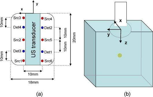
Fig. 2.

(a) Optical fibers configuration at the end of the probe (b) Position of the probe and axis representation (the basis is clockwise).

(a) Optical fibers configuration at the end of the probe (b) Position of the probe and axis representation (the basis is clockwise).