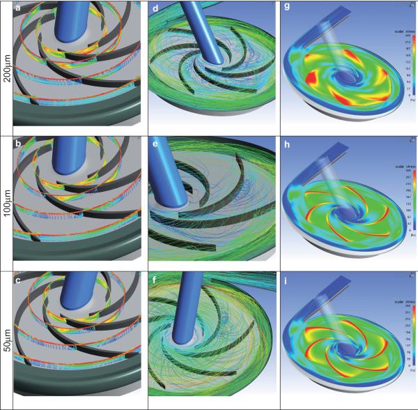
FIG. 6.
Velocity field illustrating tip leakage for three clearances studied. Left column: relative velocity vectors projected onto four radial sections of r = 7.5, 10, 15, and 20 mm, colored according to velocity magnitude. Middle column: particle pathlines. Right column: Scalar shear stress distribution on cut-plane through mean height of blade tip clearance. (Rotational direction is clockwise.)

