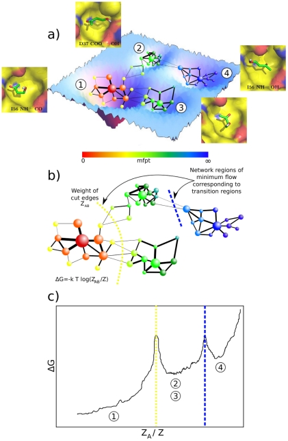
Figure 1. Illustration of the cut-based FEP [13].
(a) The high-dimensional free-energy surface is coarse-grained into nodes
of the network. Two nodes are linked if the system proceeds from one to
the other along the considered timeseries. The mean first passage time
(mfpt) is calculated for each node analytically (see text). (b) For each
value of mfpt the set A of all nodes with a lower mfpt value is defined.
The free-energy  of the
barrier between the two states formed by the nodes in A and the
remainder of the network B can be calculated by the number of
transitions
  between
nodes of either set [13]. (c) The cut-based FEP is a projection of the
free-energy surface onto the relative partition function
 , which
includes all pathways to the reference node. For each value of mfpt, the
point
  is added to the FEP. The cut-based FEP projects
the free-energy surface faithfully for all nodes to the left of the
first barrier (basin 1). After the first barrier, two or more basins
overlap (e.g., basins 2 and 3) if they have the same kinetic distance
from the reference node.

