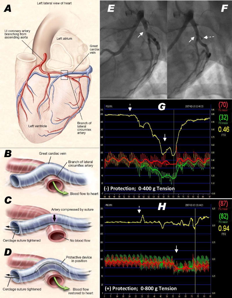
Figure 2.
Coronary artery entrapment and protection. (A,B) A typical great cardiac vein configuration passing outside a circumflex artery branch. (C) Cerclage would compress the underlying artery. (D) A protection device along the cerclage suture redistributes compressive forces away from coronary artery. (E–H) circumflex coronary artery pressure during cerclage tension without (E,G) and with (F,H) a protection device in place. (E) Angiographic stenosis (arrow) induced by cerclage and (F) the same segment during cerclage tension with a protection device (dashed arrow) in place. (G,H) Distal coronary artery pressure (Pd, depicted in green, axis on left, mm), the aortic pressure (Pa) in red, and their ratio in yellow (axis on right, displayed as fractional flow reserve). Without a protection device (G), the distal coronary pressure falls by more than half when cerclage tension (400g) is applied. (H) With the protection device in place, there is no distal pressure drop after cerclage tension is introduced (dotted arrow) until tension is sufficiently high (solid arrow) to impede mitral inflow. Panels A–D courtesy of Lydia Kibiuk, NIH Medical Arts.

