
Figure 3. Neural electrode arrays of varying thickness on simulated brain models to illustrate flexibility.
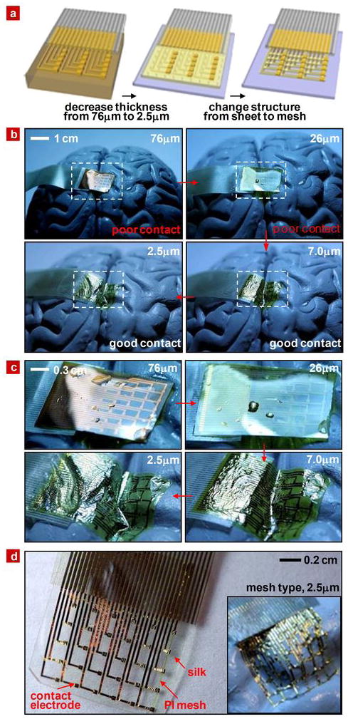
a, Schematic illustration of trends in thickness and structure that improve conformal contact. b, Series of pictures illustrating how the thickness of the electrode array contributes to conformal contact on a brain model. c, Magnified view of these pictures. d, Image of an electrode array with a mesh design on dissolvable silk substrate. Arrows indicate struts in the mesh that help to stabilize the Au interconnects after dissolution of the silk. The inset illustrates the high degree of conformal contact that can be achieved on the brain model once the silk substrate has been dissolved.