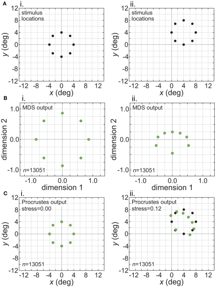
Figure 14.
Translation of stimulus configuration (small RF dispersion). This corresponds to conditions in right column of Figure 11, outside central invariant area. Left column: stimulus configuration centered at fixation [0°, 0°]. Right column: stimulus configuration centered at [4°, 4°]. (A) Physical stimulus configuration, a ring of points 8° in diameter. (B) Output of multidimensional scaling procedure. (C) Procrustes transform of MDS output. Green dots indicate recovered spatial configuration, black dots indicate original physical spatial configuration. (Black dots are obscured in left Procrustes panel.) Receptive field diameter was 24°, receptive field dispersion was 12°, and receptive field spacing was 0.1°.

