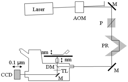
Figure 1. Inverted microscope (Olympus IX71) setup.
Diagram shows excitation and emission detection pathways and double edge arrows indicating translating elements with their approximate spatial resolution. The 488 or 514 nm lines from the argon ion laser (Innova 300, Coherent, Santa Clara, CA) are intensity modulated by the acoustoptic modulator (AOM) then linearly polarized at the Glan-Taylor (P) polarizer. The polarization rotator (PR) uses Fresnel Rhombs to rotate linear polarized light to the desired orientation. The beam enters the microscope, reflects at the dichroic mirror (DM), and is focused on the sample by the objective. The high NA objective (Olympus planapo 60X, NA = 1.45 or TIRF objective) translates along the optical axis under manual control using the microscope focus or with nm precision using a piezo nanopositioner (C-Focus, MCL, Madison, WI). The C-focus translates the objective under computer control and has an alternative feedback mode where it maintains a constant distance between the objective and a set point on the microscope stage. Sphere samples were sometimes mounted on a piezo stage to alter the distance from sample to objective along the optical-axis with nanometer precision when a moving objective was undesirable. Emitted light is collected by the objective, transmitted by the dichroic mirror, then focused by the tube lens (TL) onto the CCD camera with 6.45 µm square pixels (Orca ER, Hamamatsu Photonics, Hamamatsu-City, Japan). In some experiments, a microscope stage with leadscrew drives and stepper motors translate the CCD camera with submicrometer resolution (LEP, Hawthorne, NY).

