

Abstract
Lotus-type porous metals with aligned long cylindrical pores are fabricated by unidirectional solidification from the melt with a dissolved gas such as hydrogen, nitrogen, or oxygen. The gas atoms can be dissolved into the melt via a pressurized gas atmosphere or thermal decomposition of gaseous compounds. Three types of solidification techniques have been developed: mold casting, continuous zone melting, and continuous casting techniques. The last method is superior from the viewpoint of mass production of lotus metals. The observed anisotropic behaviors of the mechanical properties, sound absorption, and thermal conductivity are inherent to the anisotropic porous structure. In particular, the remarkable anisotropy in the mechanical strength is attributed to the stress concentration around the pores aligned perpendicular to the loading direction. Heat sinks are a promising application of lotus metals due to the high cooling performance with a large heat transfer.
Keywords: porous metals, solidification, pores, gas, mechanical properties, heat sinks
1. Introduction
Porous and foamed metals exhibit various characteristics that differ from bulk metals, including possessing a low density and large surface area. These metals are expected to be used as lightweight materials, catalyst carriers, electrodes, vibration and acoustic energy damping materials, impact energy absorption materials, etc.1) However, porous and foamed metals all suffer from deteriorating mechanical properties such as strength, stiffness, and fatigue due to the inhomogeneous pore number density distribution and pore size. Many methods, including powder metallurgy and the melt route, have been used to develop porous materials.2) Among these materials, lotus-type porous metals have attracted much attention because their long cylindrical pores align in one direction. These metals are fabricated by a unidirectional solidification process using gas from a pressurized gas atmosphere such as hydrogen (Gasar methods)3,4) or thermal decomposition of gas compounds such as hydrides.5) The pores evolve from the insoluble gas when the molten metal dissolving the gas is solidified. Compared to conventional porous metals, which have nearly spherical and isotropic pores, these metals exhibit superior mechanical properties.6)
The formation of elongated gas pores during solidification has been investigated since the study of porous ice by Chalmers.7) Air contained in water is rejected by water during the freezing process, and this air accumulates in the advancing interface until its concentration is sufficient for bubbles to nucleate. Once a bubble forms, it grows in the solidification direction to evolve a long cylindrical pore. Additionally, Knacke et al.,8) Svensson and Fredriksson,9) and Imabayashi et al.10) have studied the formation of directional pores in metals from the viewpoint of casting defects, while Shapovalov et al. have investigated the applicability of metals fabricated by high-pressure hydrogen as functional materials.3) Nakajima et al. have further fabricated various directional porous metals using solidification techniques in a pressurized gas atmosphere4) and by thermal decomposition of gaseous compounds.5) Herein because the morphology of directional porous metals resembles a lotus root, we refer to these materials as lotus-type porous metals.
This article reviews recent developments in the fabrication techniques of lotus-type porous metals, their mechanical and physical properties, and their application to heat sinks.
2. Fabrication
2.1. Solidification techniques.
Lotus metals can be fabricated by unidirectional solidification of the melt dissolving gas. The following three solidification techniques have been developed.
2.1.1. Mold casting technique.
Figure 1 schematically depicts the mold casting technique used to fabricate lotus metals; a metal inside a crucible is melted by an induction heating in a high-pressure gas atmosphere. The gas is dissolved up to the equilibrium gas concentration into the molten metal under a given gas pressure according to Sieverts’ law.11) The melt, which is saturated with gas, is poured into the mold. When part of the mold is cooled by a chiller or circulated water, the melt is solidified unidirectionally in the vicinity of the cooling part. The elongated pores can evolve and grow due to the influence of the unidirectional solidification. Moving the location of the cooling part can control the pore growth direction.
Figure 1.

Mold casting technique to fabricate lotus-type porous metals.
The morphology of lotus metals can be characterized by the porosity, pore diameter, pore length, pore distribution, etc. Variables used to control the pore morphology are the melt temperature, solidification rate, type of dissolving gas, gas pressure, etc. Hydrogen gas is most commonly used to fabricate various lotus metals and alloys: iron, nickel, aluminum, copper, magnesium, cobalt, tungsten, manganese, chromium, beryllium and their alloys, while nitrogen is used for iron, and oxygen is for silver.12) Fortunately, most base metals for commercially available, practical alloys can be made porous. Figure 2 shows typical examples of optical micrographs on the cross sections (above) and longitudinal sections (below) of lotus-type porous copper.
Figure 2.

Typical examples of optical micrographs on the cross-section of lotus copper fabricated by the mold casting technique in a hydrogen atmosphere at different pressures. Above are cross-sections perpendicular to the solidification direction and below are cross-sections parallel to the solidification direction. (a) 0.4 MPa hydrogen, porosity 44.9%, and (b) 0.8 MPa hydrogen, porosity 36.6%.
Because hydrogen is inflammable and explosive when oxygen is present, its use is inconvenient from the viewpoint of safety. Thus, employing a gas other than hydrogen is desirable. Nitrogen is an important, common alloying element to improve corrosion resistance and mechanical properties of steels.13) Iron exhibits a large nitrogen solubility difference between the solid and liquid at its melting temperature,14–16) which is similar to that of hydrogen. Utilizing the nitrogen solubility difference between the liquid and solid, lotus iron can be fabricated by above technique.17)
2.1.2. Continuous zone melting technique.
Figures 3 (a) and (b) show attempts to use the mold casting technique to produce lotus copper and stainless steel, respectively. Although lotus copper has a uniform distribution of cylindrical pores, stainless steel does not. The difference is attributed to the thermal conductivities of the metals. For metals and alloys with low thermal conductivities, although the heat from the melt is easily dissipated to the water-cooled plate during the solidification process, cooling becomes slower at the upper part of the solidified ingot because the ingot is far from the cooling part, leading to coarser pores. Consequently, only porous metals and alloys with non-uniform pore sizes and porosities can be produced as illustrated in Fig. 3(b).18)
Figure 3.

Comparison of pore evolution in lotus metals fabricated by the mold casting technique in a mixture gas of hydrogen and argon. Above are schematic drawings for pore evolution during unidirectional solidification. Below are optical micrographs of sectional views parallel to the solidification direction. Left is lotus copper fabricated in a mixture gas of 0.3 MPa hydrogen and 0.7 MPa argon. Right is lotus stainless steel (SUS304L) fabricated in a mixture gas of 1.0 MPa hydrogen and 1.0 MPa argon. (a) Homogeneous pore size and porosity are observed in copper and magnesium with a high thermal conductivity, and (b) inhomogeneous pore size and porosity are found in stainless steel with a low thermal conductivity. Magnitude of the thermal conductivity affects the solidification velocity of the melt, resulting in the different pore morphologies.
To overcome this shortcoming, Ikeda et al.19) have developed a continuous zone melting technique, which is depicted in Fig. 4(a) . While part of the specimen rod is melted by induction heating, the hydrogen (or nitrogen) gas is absorbed into the melt up to the gas equilibrium solubility in the pressurized gas atmosphere according to Sieverts’ law. Concurrently, the specimen rod is moved downward at a given velocity. In the lower part of the melt zone, solidification occurs simultaneously. Then directionally elongated pores evolve by precipitation of the insoluble gas in the solidified specimen rod. If the transfer velocity is kept constant, the solidification velocity becomes constant, which should yield a constant pore size. On the other hand, the mold casting technique cannot control the solidification velocity because the velocity is uniquely determined by its own inherent thermal conductivity. Figure 4(b) shows a sectional view of a lotus stainless steel rod (SUS304L). The pore size and porosity are almost homogeneous throughout the solidified specimen rod.
Figure 4.

(a) Schematic drawings of the melting portion of the continuous zone melting technique. (b) Sectional views of lotus stainless steels fabricated by the continuous zone melting technique in 2.0 MPa hydrogen atmosphere. Transfer velocity of the rod is 330 µm s−1. Nearly homogeneous pore size (320 µm) and porosity (40%) are obtained throughout the ingot.
2.1.3. Continuous casting technique.
When lotus metals are practically employed, mass production is indispensable. Because the aforementioned methods are not suitable due to the limitation of ingot size, we have developed a new “continuous casting technique”, which can be used to fabricate a long slab or rod (Fig. 5 ).20) The metal is melted in a crucible by radio-frequency induction heating in a high-pressure mixture gas. Then the molten metal is pulled down and solidified simultaneously through the cooled mold at a given transfer velocity. Figure 6 shows the cross sections parallel and perpendicular to the transfer direction of lotus copper fabricated in a mixture gas of hydrogen 0.25 MPa and argon 0.15 MPa with a transfer velocity of 100 mm min−1. The pore size and porosity are almost homogeneous throughout the solidified specimen slab, which is more than 700 mm long.
Figure 5.

Schematic drawing of the fabrication apparatus of lotus metals by the continuous casting technique. Large crucible and induction heating coil are located in the upper part of the pressure vessel to melt the metal and dissolve the gas into the melt, whereas the mold with the cooling part and transfer mechanism of the solidified metal slab with pinch rolls are installed in the lower part of the vessel to solidify the melt and continuously transfer the slab downward.
Figure 6.

(a) Photograph of lotus copper fabricated using the continuous casting technique, and (b) cross-sections parallel and perpendicular to the transfer direction of lotus copper fabricated in a mixture gas of hydrogen 0.25 MPa and argon 0.15 MPa by the continuous casting technique with a transfer velocity of 100 mm min−1.
Figure 7 plots the average pore diameter and porosity against the transfer velocity. The average pore diameter decreases as the transfer velocity increases, whereas the porosity is independent of the velocity. The amount of hydrogen diffusing from the liquid to the pores increases as the transfer velocity decreases. Thus, pores formed at a lower velocity are larger than those formed at a higher velocity. Unlike the pore size, the number density of the pores increases as the transfer velocity increases. Increasing the transfer velocity causes the hydrogen supersaturation of the solid–liquid interface to increase; thus, the number density of the pores increases and the pore size decreases. Therefore, the transfer velocity can control the pore size, while the hydrogen pressure can adjust the porosity.
Figure 7.

(a) Average pore diameter and (b) porosity versus the transfer velocity of lotus copper fabricated in a mixture gas of hydrogen 0.25 MPa and argon 0.15 MPa by the continuous casting technique.
2.2. Gas dissolving methods.
The fabrication process of lotus metals with unidirectional elongated pores requires the use of pressurized gas such as hydrogen, nitrogen, or oxygen. Although hydrogen gas is the most useful, it is explosive and inflammable when mixed with a small amount of oxygen. Thus, it is inconvenient for mass production in industrial applications, and lotus metal fabrication requires a safety procedure. However, an alternate technique that does not employ hydrogen gas would alleviate such difficulty. Makaya and Fredriksson21) have produced porous Fe-base materials by dissolving a CrN compound into a metallic melt of Fe-base alloy in an argon atmosphere. The decomposition of the compound leads to the dissolution of a gas into the melt, and pores are subsequently formed during solidification by the solubility gap between the liquid and solid phases. Porous metals with an isotropic pore structure are solidified from the melt in the crucible.
However, the production of lotus metals with an anisotropic cylindrical pore structure had not been investigated prior to the work of Nakajima and Ide. Nakajima and Ide5) studied the fabrication of lotus copper using titanium hydride in an argon atmosphere instead of pressurized hydrogen atmosphere. This method is called the “thermal decomposition method” (TDM). Because the solubility of hydrogen in aluminum is low, the porosity of lotus aluminum is inevitably low, on the level of 10%. Increasing the hydrogen pressure does not effectively increase the porosity, but it shrink the pores in accordance to Boyle’s law. At a lower atmospheric pressure, the porosity increases as the hydrogen pressure decreases. The advantage of TDM under a lower pressure atmosphere is that the hydrogen source can be supplied in the melt by the decomposition of compounds containing gas elements even in a vacuum, the lowest pressure.
A high-pressure chamber is unnecessary in TDM because gas compounds such as hydride and nitride are used as the dissolving gas source. Typically the atmosphere during melting and solidification is argon or a vacuum to prevent oxidation and impurity inclusions. To fabricate lotus copper via TDM in 0.1 MPa argon, a few pellets of titanium hydride are placed on the bottom plate of the cooled mold. Molten copper, which is melted by radio-frequency induction heating in a graphite crucible, is poured into the mold (Fig. 8 ). During the unidirectional solidification, the hydride decomposes into titanium and hydrogen. The insoluble hydrogen in the solidified phase evolves into pores, while the titanium may form titanium oxide, which serves as nucleation sites for the gas pores. Figure 9 shows optical micrographs of the cross-sectional views of lotus copper parallel and perpendicular to the solidification direction. The pore growth direction is coincident to the direction of the unidirectional solidification, which is consistent with the conventional high-pressure gas method (PGM). This result reveals that TDM and PGM have similar principal mechanisms for pore evolution.
Figure 8.

Schematic drawing of the principle to fabricate lotus metals using the thermal decomposition method and a gas compound via the mold casting technique. Pellets of titanium hydride are set in the mold. Molten copper poured from the crucible into the mold reacts with the hydride, and hydrogen dissolves in the melt simultaneously. When the melt solidifies in the upward direction, insoluble hydrogen evolves directional pores.
Figure 9.

Optical micrographs of cross-sectional views of lotus copper (upper views) perpendicular and (lower views) parallel to the solidification direction. Mass of titanium hydride added to the melt of 200 g copper is (a) 0.075 g, (b) 0.10 g, (c) 0.125 g, and (d) 0.25 g. Melting and subsequent solidification are carried out in 0.1 MPa argon atmosphere.
The porosity has been investigated as a function of the mass of titanium hydride. Adding 0.10 g of the hydride abruptly increases the porosity, but the addition of more titanium hydride causes the porosity to become constant near 55%. When 0.10 g of titanium hydride is added to 200 g in the melt of copper, the concentration of hydrogen is 0.128 at.%, which is comparable to the maximum solubility of hydrogen in liquid copper near the melting point.22) Therefore, even if more than 0.10 g of the hydride is added, the supersaturated hydrogen may generate gas bubbles, which are then liberated from the melt into the atmosphere.
For lotus aluminum fabricated via TDM, 0.2 g of a gas compound such as calcium hydroxide, sodium bicarbonate, or titanium hydride has been added to 100 g molten aluminum in a vacuum and solidified unidirectionally. Figure 10 shows the microstructure of lotus aluminum on cross sections parallel and perpendicular to the solidification direction.23) Pores with an average size of 400, 268, and 1086 µm are evolved using calcium hydroxide, sodium bicarbonate, and titanium hydride, respectively. The porosity is as high as 20%, regardless of the gas compound. Although the pore size is small, as little as 400 µm, its distribution is homogeneous in lotus aluminum when employing calcium hydroxide and sodium bicarbonate. In contrast, the pore size is as large as 1000 µm and its distribution is not uniform when employing titanium hydride.
Figure 10.

Optical micrographs of lotus aluminum fabricated via the thermal decomposition method using different compounds by the mold casting technique in vacuum at 1023 K. Upper and lower micrographs are the cross sections perpendicular and parallel to the solidification direction, respectively.
Table 1 is a compilation of the decomposition reactions of the three compounds in an aluminum melt. Calcium hydroxide or sodium bicarbonate decomposes into compounds (CaO, Na2CO3), carbon dioxide, and vapor, and the latter further decomposes into metallic oxide and hydrogen. These reactions produce small pores with a homogeneous distribution. On the other hand, titanium hydride decomposes directly into titanium and hydrogen, resulting in large pores with an inhomogeneous distribution. Although the reasons for this difference are currently unclear, the evolution of small pores with a homogeneous distribution may be attributed to the existence of oxide particles, which may serve as pore nucleation sites. To investigate the content of pore gas, gas analysis has been conducted; hydrogen is the pore formation source for titanium hydride, calcium hydroxide, and sodium bicarbonate.
Table 1.
Decomposition reactions and temperature of gaseous compounds
| Reactions | Decomposition temperature (K) |
Gas atoms or molecules to be dissolved and bubbled |
|---|---|---|
| Ca(OH)2 → CaO + H2O | 853 | H |
| H2O → metallic oxide + 2H | ||
| 2NaHCO3 → Na2CO3 + H2O + CO2 |
473 | H, CO, O |
| H2O → metallic oxide + 2H | ||
| TiH2 → Ti + 2H | 723 | H |
3. Properties
Conventional porous metals, including foamed metals, cellular metals, and sintered metals, possess almost nearly spherical pores and exhibit isotropic mechanical properties. Moreover, the shape of the pores is not always circular and can be distorted, leading the stress to easily concentrate, which deteriorates the strength. In addition, the non-uniform distribution of pore size and porosity causes to the stress to concentrate, further degrading the strength. These behaviors lead to inferior mechanical properties.
Unlike conventional porous metals, lotus metals have elongated cylindrical pores aligned in one direction. Additionally, their various mechanical properties remarkably differ from those of isotropic porous materials, and exhibit significant anisotropic behavior. Several topics regarding the mechanical and physical properties are described below.
3.1. Elastic properties.
Lotus metals macroscopically exhibit hexagonal (transverse-isotropy) elastic symmetry with the c-axis parallel to the pore direction.24,25) In this case, there are five independent elastic constants, c11, c33, c13, c44, and c66 = (c11 − c12)/2. To determine all of them, resonant ultrasound spectroscopy (RUS)26,27) and mode-selective electromagnetic acoustic resonance (EMAR)28) techniques have been used. The elastic constants are determined through iterative calculations from the resonant spectrum obtained by this RUS–EMAR combination technique.
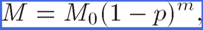
Figure 11 shows the porosity dependence of Young’s moduli E⊥ and E// and the elastic stiffness c11, c33, c13, c44, and c66 of lotus iron with hydrogen or nitrogen pores where E// and E⊥ indicate Young’s moduli parallel and perpendicular to the pore direction, respectively. Besides the porosity dependence of lotus copper,24) E// decreases linearly, whereas E⊥ drops steeply in the small porosity region. After extensive research on the effective physical properties (e.g., the electrical conductivity, yield stress, and elastic modulus) of porous materials, their porosity dependencies have been experimentally found to follow the power-law formula29–33)
 |
(1) |
where M and M0 are the physical properties of the porous and nonporous materials, respectively, and m is the coefficient empirically determined. The solid and broken lines in Fig. 11 indicate the fit of Eq. [1] to the measured data. Thus, it is concluded that Eq. [1] holds for the effective elastic constants of anisotropic porous metals.
Figure 11.

Porosity dependence of (a) two Young’s moduli, E// in the direction parallel to the x3-axis and E⊥ in the direction perpendicular to the x3-axis, and the elastic stiffness coefficients, (b) c11, c33, c13, (c) c44, and c66 of lotus iron. Transverse isotropy condition c66 = (c11 − c12)/2 holds. Each line is obtained by fitting Eq. [1] to the measurements.
3.2. Tensile strength.
Little data is available on the mechanical properties of this type of porous metal. Wolla and Provenzano34) and Simone and Gibson35) have measured the tensile strength of porous copper with the pore orientation parallel to the tensile direction. However, their data is largely scattered, which may be attributed to microstructural variations within each specimen as well as in between the specimens. Furthermore, an investigation on the anisotropy of the mechanical properties of lotus metals with elongated cylindrical pores has yet to be conducted. Hyun et al.6) have measured the ultimate tensile strength and the yield strength of lotus copper, and elucidated the uniaxial tensile behavior of lotus copper with the pore orientation parallel and perpendicular to the tensile direction. Moreover, the fracture surfaces of selected tensile test specimens have been investigated to obtain information about the fracture mode of these materials.
Figure 12 plots the ultimate tensile strength of specimens with cylindrical pore orientation parallel to the tensile direction against porosity. The data points for the ultimate tensile strengths lie on a straight line passing through the point of 0 MPa at a porosity of 100%, indicating that the presence of pores does not change the specific ultimate tensile strength. This fact indicates that the pores with axes aligned parallel to the tensile direction do not cause the stress to concentrate in tensile specimens. Thus, the simple rule of a mixture of the empty pores and the solid body can be applied to these specimens. Figure 12 also plots the ultimate strengths of specimens with cylindrical pores perpendicular to the tensile direction versus porosity. The ultimate tensile strength of the specimen with pores perpendicular to the tensile direction is much lower than that of specimen with pores parallel to the tensile direction at a given porosity.
Figure 12.

Porosity dependence of the ultimate tensile strength of lotus copper parallel and perpendicular to the pore axis.
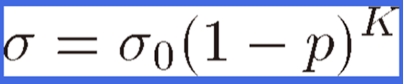
Boccaccini et al.36) have suggested an empirical relation in the form of
 |
(2) |
to describe the variation in the strength with porosity p, where K is a constant that depends on the materials and fabrication method. K is related to the stress concentration around the pores in the porous materials. This formula is identical to Eq. [1].
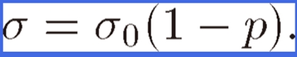
For a specimen with cylindrical pores aligned parallel to the tensile direction, the value of K approaches unity; stress does not concentrate. Thus, Eq. [2] can be simply rewritten as
 |
(3) |
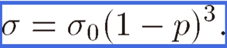
However, for a specimen with cylindrical pores oriented perpendicular to the tensile direction, the value of K approaches 3. Then the stress concentration can be expressed as
 |
(4) |
Figure 12 shows the ultimate tensile strength evaluated from Eqs. [3] and [4]. The experimental results agree well with the dotted lines estimated from Eqs. [3] and [4]. Thus, the tensile strength for lotus copper with cylindrical pores parallel to the tensile direction is higher than that perpendicular to the tensile direction. Hence, the anisotropy of the strength is attributed to the stress concentration around the pores. Because such anisotropy has been observed in lotus magnesium, iron and its alloys, anisotropy is a characteristic of lotus metals.
Here, we have to remark on the abnormal tensile properties of lotus iron fabricated by nitrogen. Hyun et al.37) fabricated lotus iron, not only using hydrogen gas but also by nitrogen gas. They found lotus iron exhibits a superior mechanical strength. The tensile strength of lotus iron with cylindrical pores parallel to the tensile direction, which was fabricated in hydrogen, obeys the line fitted to the constant specific strength; the strength of 100 MPa in about 50% porosity. However, the tensile strength of lotus iron fabricated in nitrogen is twice the predicted value. The high strength is ascribed to solid solution strengthening due to the solute nitrogen atoms, which contains 0.0873 mass%.
The anisotropic tensile deformation of lotus copper has been recently investigated with an emphasis on crack formation during deformation.38) The microscopic deformation was analyzed by an acoustic emission (AE) method, which can detect crack formation. A broadband AE sensor is placed on the specimen during tensile tests to generate an AE signal by deformation. Figure 13 shows the amplitudes of the burst AE signals detected during the deformation of lotus copper and the corresponding stress–strain curves for (a) parallel loading and (b) perpendicular loading. The elongation and peak stress (ultimate tensile strength) for perpendicular loading are much smaller than those for parallel loading, which is consistent with the aforementioned result for tensile strength. It is significant that many burst AE signals are detected after yielding to a fracture, regardless of the loading direction. Unlike lotus copper, burst AE signals are not detected in nonporous copper, as shown in Fig. 13(c). Thus, the burst AE signals associated with lotus copper can be attributed to pore-related crack formation. The cumulative AE counts per unit of nominal strain for perpendicular loading are larger than those for parallel loading; the cracks are formed more easily under perpendicular loading.
Figure 13.

Amplitude of the burst AE signals detected during deformation and the corresponding stress–strain curves for lotus copper under (a) parallel and (b) perpendicular loadings. (c) Amplitudes of the burst AE signals detected loadings parallel and perpendicular to the solidification direction are applied to nonporous copper.
The changes in the cross-section, ΔS, during parallel and perpendicular tensile loading for lotus copper and nonporous copper have also been measured. The value of ΔS for perpendicular loading is smaller than that for parallel loading, and the values of ΔS in lotus copper are much smaller than those in nonporous copper. These observations imply that under perpendicular loading, lotus copper macroscopically behaves as a semi-brittle material, although nonporous copper is ductile, whereas under parallel loading, lotus copper behaves in an intermediate manner between deformation under perpendicular loading and that of nonporous copper. These deformation behaviors of lotus copper are qualitatively consistent with that of a ductile metal, which tends to deform as a brittle material under high stress triaxiality.39)
3.3. Sound absorption.
Sound absorption materials with advanced performances to noises are required for car mufflers, air-conditioner parts, pump chambers, elevated roads, etc. Currently glass wool and foamed aluminum with closed pores are the most commonly marketed sound absorbing materials. In most cases, these materials have a low strength, but a good sound absorption capacity. The development of a sound absorbing material with comprehensive characteristics such as high strength, lightweight, and good sound absorption capacity is desirable. To investigate whether lotus metals exhibit significant sound absorption characteristics, Xie et al.40–42) have measured the sound absorption coefficients of lotus magnesium and copper plates by a standing-wave method; the details are provided in JIS A1405-1963 standards.43) The absorption coefficient depends on the angle between the material surface and the incident sound wave. In their experiments, the specimen surface was perpendicular to the incident sound wave, and the specimen was set on a rigid wall in the sound tube. A pure sound with a single frequency was generated from a speaker installed at the other end. The standing-wave is caused by the interference between the incidence and reflection waves in the tube.
The absorption coefficients for lotus copper α0 have been measured as functions of pore diameter, porosity, and specimen thickness in the frequency range from 125 Hz to 4 kHz. The results can be summarized by:
-
•
α0 increases as the pore diameter decreases from 660 µm to 460 µm.
-
•
α0 increases as porosity increases from 43% to 62%.
-
•
α0 increases as thickness increases.
A similar tendency has been observed for lotus magnesium.41,42) Figure 14 compares the absorption coefficients of lotus copper, foam aluminum, and glass wool with the same thickness specimen and frequency region. Similar to commercially available glass wool and foam aluminum, lotus metals exhibit a superior sound absorbing capacity. The foam aluminum is composed of numerous independent closed pores. For a high sound absorption, continuous pores are necessary so that minute cracks are introduced by rolling to connect the pores of the foam aluminum.44)
Figure 14.

Comparison of the sound absorption coefficients for various materials with thickness of 20 mm.
It is thought that the viscosity resistance of air in the pores plays an important role in absorbing sound for a porous material. Sound is absorbed by the resistance in the fiber and the thin space of the pores when it enters into the open pores in porous materials.45) Additionally, sound is absorbed by the disturbance of the movement of air. The absorption of sound in a porous material is mainly due to the consumption of sound energy by the viscosity and thermal conduction when sound is propagating into the thin tube.
3.4. Thermal conductivity.
To use lotus copper effectively as heat sinks, which is discussed below, it is important to know its effective thermal conductivity and to consider the pore effect on heat flow. There are two typical methods to measure effective thermal conductivity keff of materials: an unsteady-state method (e.g., laser-flash method) and a steady-state method. In the former, the time change of the temperatures on the front and reverse sides of the specimen irradiated by a laser-flash is measured to determine keff. This method is suitable to measure keff of homogeneous and isotropic solid materials.46) On the other hand, in the latter method, a constant temperature on the front and reverse sides of the specimen is maintained to measure the steady-state heat flow through the specimen. This method is suitable to measure keff of inhomogeneous and anisotropic materials.47) Thus, the steady-state method has been adopted to measure keff of lotus metals.48) In measurements using the steady-state method, the specimen settles between a heater block and cooling block, and the temperatures at each block and the specimen are detected by thermocouples and the temperature gradient is measured.
The effective thermal conductivity of lotus copper keff is defined by
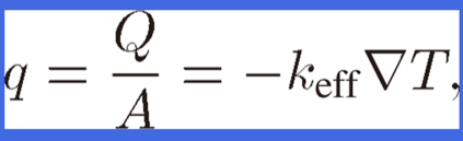 |
(5) |
where q is the heat flux from heat flow Q divided by the heat flowing through cross-sectional area A in lotus copper and T is the temperature in lotus copper. The tensor keff is orthorhombic and is expressed as
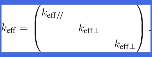 |
(6) |
Because keff of lotus copper is anisotropic, the parallel and perpendicular effective thermal conductivities, keff// and keff⊥, of lotus copper are defined as the thermal conductivities for the heat flow parallel and perpendicular to the pore axis, respectively. Because the heat flow cross-sectional areas parallel to the pore axis in lotus copper are proportional to (1 − p), keff// is expressed as
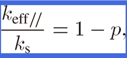 |
(7) |
where ks is the thermal conductivity of nonporous copper. Behrens49) has derived keff of composite materials with orthorhombic symmetry. By applying his equation to the thermal conductivity of lotus copper, keff⊥ can be expressed as
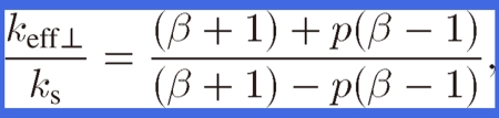 |
(8) |
where β (= kp/ks) is the conductivity ratio; that is, it is the pore conductivity kp divided by material conductivity ks of lotus copper. Because the thermal conductivity of the hydrogen gas or air in the pores of lotus copper is negligible compared to that of the lotus material, the effective thermal conductivity of lotus copper is derived by the following equation where β = 0 in the above equation
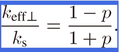 |
(9) |
Han and Cosner50) have performed a numerical study on keff of fibrous composites using a unit-cell approach under a uniform fiber diameter condition. Because the diameter of lotus copper is distributed around a certain range, the numerical simulation for the thermal conductivity perpendicular to the pores under a nonuniform pore diameter condition was conducted to verify the applicability of Eq. [9] to lotus copper.
Figure 15 compares the experimental data and the results evaluated by the analytical equation in Eq. [7] for thermal conductivity parallel to the pores. The experimental data for keff// agrees well with the analytical results derived from the assumption that the heat flow through the cross-sectional area parallel to the pore axis is proportional to (1 − p). A value of 335 W/(m K) for thermal conductivity ks of the lotus copper material is used for comparison. Figure 15 compares the experimental data and Eq. [9] where effective thermal conductivity keff⊥ perpendicular to the pores is lower than that of the parallel ones (keff//), and is 40% of lotus copper material ks with a porosity of 40%. The analytical values evaluated by Eq. [9] is consistent with the experimental data, indicating that Eq. [9] can be used to predict the effective thermal conductivity perpendicular to the pores of lotus copper within an experimental accuracy of ±10%. The results show that lotus copper displays anisotropy of the effective thermal conductivity. The effective thermal conductivity keff⊥ perpendicular to the pores is lower than that of parallel ones (keff//).
Figure 15.

Comparison of the experimental data of the effective thermal conductivity of lotus copper parallel and perpendicular to the pore axis with the analytical data.
4. Various applications of lotus metals
4.1. Heat sinks.
In recent years, because the heat dissipation rates in power devices and high frequency electronic devices have been increasing, heat sinks with high heat transfer performances are necessary to cool these devices. Heat sinks utilizing microchannels with a channel diameter of several tens of microns are expected to provide excellent cooling performances because higher heat transfer capacities are obtained with smaller channel diameters.51,52) Therefore, a porous material with open pores is preferable for three-dimensional microchannels due to economical factors and the higher surface area per unit volume. Various porous materials such as sintered porous metals, cellular metals, and fibrous composites have been investigated for heat sink applications.53) However, heat sinks using such porous materials have a high pressure drop due to the complex cooling fluid flow through the pores.
Among described porous materials, a lotus metal with straight pores is preferable for heat sinks due to the small pressure drop of the cooling fluid flowing through the pores. Chiba et al. have investigated the heat transfer capacity of a heat sink using lotus copper for air cooling54) and water cooling.55) Figures 16 (a) and (b) show the experimental apparatuses used to measure the heat transfer capacity of heat sinks for air cooling and water cooling, respectively. The heat sink consists of lotus copper fins brazed on one side of a copper base plate and a heating block with a heater soldered to the other side of the base plate. In Fig. 16(a), cooling air is blown by a blower into the test duct where the heat sink is located. In Fig. 16(b), cooling water is circulated by a circulator pump through a filter and the test duct where the heat sink is located. Inlet temperature of the cooling water Ti, temperature of the copper base plate Tb, and outlet temperature of the cooling water To are measured by K-type thermocouples. Thus, the heat transfer capacity by heat transfer hi based on the base plate area Ab can be evaluated as
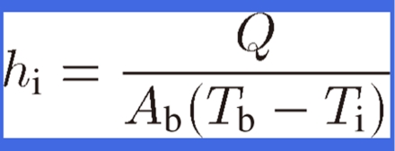 |
(10) |
where Q is the heat transfer rate evaluated by deducting the heat loss through the thermal insulator around the heater from the heat input.
Figure 16.

Experimental apparatuses to measure the heat transfer capacity for (a) air-cooling heat sink and (b) water-cooling heat sink.
The heat transfer coefficients hb, which are based on the base-plate surface area for the heat sink for air cooling, are measured as a function of the inlet velocity of the blowing air. Figure 17(a) shows the results as well as that for conventional groove fins, which are composed of copper with a 3 mm fin gap, a 1 mm fin thickness, and a 20 mm fin height. The prediction54) for a lotus copper heat sink agrees well with the experimental data, with an accuracy of ±5%. The experimental data for a lotus copper heat sink with a thickness L = 1 mm shows a very large heat transfer coefficient of 5000 W/(m2 K) under an inlet velocity of 1.0 m/s, which is 13.2 times higher than that for conventional groove fins.54)
Figure 17.

(a) Comparison of the heat transfer coefficients of air-cooling heat sinks between lotus copper fins and conventional groove fins. (b) Comparison of the heat transfer coefficients of water-cooling heat sinks among lotus copper fins, conventional groove fins, and microchannels.
In lotus copper heat sinks for water cooling, the heat transfer capacity of three types of heat sinks have been investigated: one with conventional groove fins, one with smaller groove fins (microchannels), and one using lotus copper. Conventional groove fins have a fin gap of 3 mm and a fin thickness of 1 mm, whereas the microchannels have a fin gap of 0.5 mm and a fin thickness of 0.5 mm. Lotus copper fins have pores with an average diameter of 0.3 mm and a porosity of 39%. The heat transfer capacity of the conventional groove fin is the only one to be calculated. As shown in Fig. 17(b), the experimental data for the lotus copper heat sink exhibits a very large heat transfer coefficient of 80000 W/(m2 K) under velocity u0 of 0.2 m/s, which is 1.7 times higher than that for the microchannels and 6.5 times higher than that of the conventional groove fins.55) Therefore, it is concluded that a lotus copper heat sink has the most potential for higher power electronic devices.
4.2. Golf putters and other potential applications.
Lotus copper was commercialized as golf putters manufactured by Ryobi Corporation in 2002 and Lotus Alloy Company in 2008. Lotus copper was placed into the putter flame as an inserted material that shows superior damping capacity. It is said that one feels a mild touch when the golf ball is hit.
In addition to golf putters, other potential applications include artificial teeth and machine tools. Lotus titanium can be utilized to create pores with diameters of 150–200 µm, and bony tissues can be grown in these pores to enhance the holding force. Lotus carbon steel slabs can be used as saddles for machine tools because lightweight materials with sufficient stiffness and vibration-damping can reduce the operating costs by 20%.
5. Conclusion and perspective
This review article summarizes the present status of research on lotus metals with directionally elongated pores. Compared to conventional porous metals with isotropically, almost spherical pores, lotus metals exhibit peculiar features, which are derived from the alignment of the long pores, such as being lightweight and exhibiting superior mechanical strength as well as vibration-damping. Thus, these materials have potential as advanced engineering materials from the viewpoints of materials science and practical applications.
Acknowledgements
The author expresses his appreciation to Prof. S. K. Hyun, Dr. T. Ikeda, Dr. M. Tane, Dr. T. Ide, Dr. S. Suzuki of Osaka University, Dr. H. Chiba of Mitsubishi Electric Corporation and Prof. T. Ogushi of Hiroshima International University. The present work was supported by Priority Assistance for the Formation of Worldwide Renowned Centers of Research—The Global COE Program (Project: Center of Excellence for Advanced Structural and Functional Materials Design) from the Ministry of Education, Culture, Sports, Science and Technology (MEXT) of Japan.
Profile
Hideo Nakajima was born in 1949, and received his Bachelor’s degree in 1971 and Ph.D. from Tohoku University in 1977. Then, he was a postdoctoral associate at Rensselaer Polytechnic Institute, USA until 1980. For 1980 to 1992, he was a research associate and an associate professor at Institute for Materials Research, Tohoku University. In 1992, he moved to Iwate University as a professor. Since 1996, he has been a professor of Institute of Scientific and Industrial Research, Osaka University. Since 2010 he is vice-president of Japan Institute of Metals.
Until 2000 he had investigated in the area of atomic diffusion in metals, intermetallic compounds and quasicrystals to elucidate various diffusion mechanisms. In 1993, he started his research focused on porous metallic materials, in particular, on fabrication, mechanical and physical properties, and industrial applications from motives for utilizing casting defects effectively. He performed pioneering work on fabrication and properties of porous metals. He developed novel solidification techniques of continuous zone melting and continuous casting techniques to fabricate lotus-type porous metals with uniform pore size and porosity. Furthermore, he invented a new fabrication method of lotus metals by thermal decomposition of gaseous compounds, which is simple and safe method and suitable for mass production of lotus metals. The conventional method has flammable and explosive risk because of use of high-pressure hydrogen gas. He clarified anisotropic behavior of elastic, mechanical properties, thermal conductivity, electrical conductivity, and magnetic properties. He found superior mechanical properties, peculiar features of damping and energy absorbing properties, and biocompatibility inherent from lotus structure. He was awarded the Meritorious Honor Award in 1992, the Tanigawa-Haris Prize in 2004 and Masumoto Hakaru Prize in 2008 from Japan Institute of Metals, Kansai Venture Business Grand Prix from Kansai Venture Business Society in 2001, Prize for Science and Technology, the Commendation for Science and Technology by the Minister of Education, Culture, Sports, Science and Technology in 2007, and the Medal with Purple Ribbon in 2009.
References
- 1).Banhart J. (2001) Manufacture, characterization and application of cellular metals and metal foams. Prog. Mater. Sci. 46, 559–632 [Google Scholar]
- 2).Ashby, M.F., Evans, A.G., Fleck, N.A., Gibson, L.J., Hutchinson, J.W. and Wadley, H.N.G. (2000) Metal Foams: A Design Guide. Butterworth-Heinemann, Woburn. [Google Scholar]
- 3).Shapovalov V. (1994) Porous metals. MRS Bull. XIX, 24–28 [Google Scholar]
- 4).Nakajima H., Hyun S.K., Ohashi K., Ota K., Murakami K. (2001) Fabrication of porous copper by unidirectional solidification under hydrogen and its properties. Colloids Surf. A, Physicochem. Eng. Asp. 179, 209–214 [Google Scholar]
- 5).Nakajima H., Ide T. (2008) Fabrication of porous copper with directional pores through thermal decomposition of compounds. Metall. Mater. Trans., A 39A, 390–394 [Google Scholar]
- 6).Hyun S.K., Murakami K., Nakajima H. (2001) Anisotropic mechanical properties of porous copper fabricated by unidirectional solidification. Mater. Sci. Eng. A 299, 241–248 [Google Scholar]
- 7).Chalmers B. (1959) How water freezes. Sci. Am. 200, 114–122 [Google Scholar]
- 8).Knacke O., Probst H., Wernekinck J. (1979) On blow-hole formation during solidification of silver melts containing oxygen and copper melts containing oxygen and sulphur. Z. Metallk. 70, 1–8 [Google Scholar]
- 9).Svensson, I. and Fredriksson, H.S. (1983) Effect of hydrogen and nitrogen on formation of pores in iron. In Solidification Technology on the Foundry and Cast House. The Metals Society, Coventry, pp. 376–380. [Google Scholar]
- 10).Imabayashi M., Ichimura M., Kanno Y. (1983) Hydrogen in pure aluminum solidified unidirectionally. Trans. Jpn. Inst. Metals 24, 93–100 [Google Scholar]
- 11).Reed-Hill, R.E. (1964) Physical Metallurgy Principles. D.Van Nostrand Company, Princeton, p. 393. [Google Scholar]
- 12).Nakajima H. (2007) Fabrication, properties and application of porous metals with directional pores. Prog. Mater. Sci. 52, 1091–1173 [DOI] [PMC free article] [PubMed] [Google Scholar]
- 13).Simmons J.W. (1996) Overview: high-nitrogen alloying of stainless steels. Mater. Sci. Eng. A 207, 159–169 [Google Scholar]
- 14).Massalski, T.B. (eds.) (1986) In Binary Alloy Phase Diagram. American Society for Metals, Metals Park, p. 1079. [Google Scholar]
- 15).Levinsky, Y. (eds.) (1997) In Pressure Dependent Phase Diagram of Binary Alloys. ASM International, Materials Park, p. 693. [Google Scholar]
- 16).Satir-Kolorz A.H., Feichtinger H.K. (1991) On the solubility of nitrogen in liquid iron and steel alloys using elevated pressure. Z. Metallk. 82, 689–697 [Google Scholar]
- 17).Hyun S.K., Nakajima H. (2002) Fabrication of porous iron by unidirectional solidification in nitrogen atmosphere. Mater. Trans. 43, 526–531 [Google Scholar]
- 18).Ikeda T., Tsukamoto M., Nakajima H. (2002) Fabrication of lotus-type porous stainless steel by unidirectional solidification under hydrogen atmosphere. Mater. Trans. 43, 2678–2684 [Google Scholar]
- 19).Ikeda T., Aoki T., Nakajima H. (2005) Fabrication of lotus-type porous stainless steel by continuous zone melting technique and mechanical property. Metall. Mater. Trans., A 36A, 77–86 [Google Scholar]
- 20).Park J.S., Hyun S.K., Suzuki S., Nakajima H. (2007) Effect of transference velocity and hydrogen pressure on porosity and pore morphology of lotus-type porous copper fabricated by a continuous casting technique. Acta Mater. 55, 5646–5654 [Google Scholar]
- 21).Makaya A., Fredriksson H. (2005) Study on the production of Fe-Cr-Mn-C-Si foam by nitrogen solubility difference between the liquid and solid phases. Mater. Sci. Eng. A 413–414, 533–537 [Google Scholar]
- 22).Fromm, E. and Gebhardt, E. (1976) Gases and Carbon in Metals. Springer, Berlin. [Google Scholar]
- 23).Kim S.Y., Park J.S., Nakajima H. (2009) Fabrication of lotus-type porous aluminum through thermal decomposition method. Metall. Mater. Trans., A 40A, 937–942 [Google Scholar]
- 24).Ichitsubo T., Tane M., Ogi H., Hirao M., Ikeda T., Nakajima H. (2002) Anisotropic elastic constants of lotus-type porous copper: measurements and micromechanics modeling. Acta Mater. 50, 4105–4115 [Google Scholar]
- 25).Tane M., Ichitsubo T., Nakajima H., Hyun S.K., Hirao M. (2004) Elastic properties of lotus-type porous iron: acoustic measurement and extended effective-mean-field theory. Acta Mater. 52, 5195–5201 [Google Scholar]
- 26).Demarest H.H., Jr. (1969) Cube-resonance method to determine the elastic constants of solids. J. Acoust. Soc. Am. 49, 768–775 [Google Scholar]
- 27).Ohno I. (1976) Free vibration of a rectangular parallelepiped crystal and its application to determination of elastic constants of orthorhombic crystals. J. Phys. Earth 24, 355–379 [Google Scholar]
- 28).Ogi H., Ledbetter H., Kim S., Hirao M. (1999) Contactless mode-selective resonance ultrasound spectroscopy: electromagnetic acoustic resonance. J. Acoust. Soc. Am. 106, 660–665 [Google Scholar]
- 29).Phani K.K. (1986) Young’s modulus-porosity relation in gypsum systems. Am. Ceram. Soc. Bull. 65, 1584–1586 [Google Scholar]
- 30).Kovacik J. (1998) The tensile behaviour of porous metals made by gasar process. Acta Mater. 46, 5413–5422 [Google Scholar]
- 31).Kovacik J., Simancik F. (1998) Aluminium foam-modulus of elasticity and electrical conductivity according to percolation theory. Scr. Mater. 39, 239–246 [Google Scholar]
- 32).Rotter C.A., Smith C.S. (1966) Ultrasonic equation of state of iron I. low pressure, room temperature. J. Phys. Chem. Solids 27, 267–276 [Google Scholar]
- 33).Simmons, G. and Wang, H. (eds.) (1971) Single Crystal Elastic Constants and Calculated Aggregate Properties: A Handbook. 2nd ed. MIT Press, Cambridge. [Google Scholar]
- 34).Wolla J.M., Provenzano V. (1995) Mechanical properties of gasar porous copper. Mater. Res. Soc. Symp. Proc. 371, 377–382 [Google Scholar]
- 35).Simone A.E., Gibson L.J. (1996) The tensile strength of porous copper made by the gasar process. Acta Metall. 44, 1437–1447 [Google Scholar]
- 36).Boccaccini A.R., Ondracek G., Mombello E. (1995) Determination of stress concentration factors in porous materials. J. Mater. Sci. Lett. 14, 534–536 [Google Scholar]
- 37).Hyun S.K., Ikeda T., Nakajima H. (2004) Fabrication of lotus-type porous iron and its mechanical properties. Sci. Technol. Adv. Mater. 5, 201–205 [Google Scholar]
- 38).Tane M., Okamoto R., Nakajima H. (2010) Tensile deformation of anisotropic porous copper with directional pores. J. Mater. Res. 25, 1975–1982 [Google Scholar]
- 39).Agogino A.M. (1978) Notch effects, stress state and ductility. J. Eng. Mater. Tech. Trans. ASME 100, 348–355 [Google Scholar]
- 40).Xie Z.K., Ikeda T., Okuda Y., Nakajima H. (2004) Sound absorption characteristics of lotus-type porous copper fabricated by unidirectional solidification. Mater. Sci. Eng. A 386, 390–395 [Google Scholar]
- 41).Xie Z.K., Ikeda T., Okuda Y., Nakajima H. (2004) Characteristics of sound absorption in lotus-type porous magnesium. Jpn. J. Appl. Phys. 43, 7315–7319 [Google Scholar]
- 42).Xie Z.K., Ikeda T., Okuda Y., Nakajima H. (2004) Measurement and analysis of sound absorption of porous magnesium. Mater. Sci. Forum 449–452, 661–664 [Google Scholar]
- 43).Kimura, S. (1977) Architectural Sound and Anti-Noise Plan. Shokokusha Publishing Co., Ltd., Tokyo, p. 142 (in Japanese). [Google Scholar]
- 44).Lu T.J., Hess A., Ashby M.F. (1999) Sound absorption in metallic foams. J. Appl. Phys. 85, 7528–7539 [Google Scholar]
- 45).Nisimaki, S. (1971) Electro-Acoustics and Vibration. Corona Publishing Co., Ltd., Tokyo, p. 79. [Google Scholar]
- 46).Japanese Industrial Standards (2005) Methods for measuring thermal diffusivity of metals by the laser flash method. JIS-H7801.
- 47).Japanese Industrial Standards (2008) Methods for thermal conductivity test of porous metals. JIS-H7903.
- 48).Ogushi T., Chiba H., Nakajima H., Ikeda T. (2004) Measurement and analysis of effective thermal conductivities of lotus-type porous copper. J. Appl. Phys. 95, 5843–5847 [Google Scholar]
- 49).Behrens E. (1968) Thermal conductivities of composite materials. J. Compos. Mater. 2, 2–17 [Google Scholar]
- 50).Han L.S., Cosner A.A. (1981) Effective thermal conductivities of fibrous composites. J. Heat Transfer 103, 387–392 [Google Scholar]
- 51).Weilin Q., Mala G.M., Dongqing L. (2000) Pressure-driven water flows in trapezoidal silicon microchannels. Int. J. Heat Mass Transfer 43, 353–364 [Google Scholar]
- 52).Tso C.P., Mahulokar S.P. (2000) Experimental verification of the role of Brinkman number in microchannels using local parameters. Int. J. Heat Mass Transfer 43, 1837–1849 [Google Scholar]
- 53).Hunt M.L., Tien C.L. (1988) Effect of thermal dispersion on forced convection in fibrous media. Int. J. Heat Mass Transfer 31, 301–309 [Google Scholar]
- 54).Chiba H., Ogushi T., Nakajima H. (2010) Heat transfer capacity of lotus-type porous copper heat sink for air cooling. J. Thermal Sci. Tech. 5, 222–237 [Google Scholar]
- 55).Chiba H., Ogushi T., Nakajima H., Ikeda T. (2004) Heat transfer capacity of lotus-type porous copper heat sink. Jpn. Soc. Mech. Eng. Int. J. Ser. B 47, 516–521 [Google Scholar]