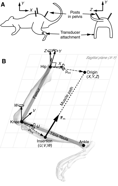
Fig. 1.
(A) Experimental setup. The pelvis was immobilized by three posts: one in the rostral and one in the caudal end of the contralateral pelvis and one in the rostral end of the ipsilateral pelvis. A six-dimensional force and moment transducer was secured to an attachment cemented to the distal tibia on the left hindlimb. In this configuration, the X-, Y- and Z-axes are aligned with the rostral–caudal, dorsal–ventral and medial–lateral directions, respectively. (B) Kinematic structure and coordinate frames defined for the hindlimb. The origin of the muscle is defined as a point (X,Y,Z) in a coordinate frame with an origin at the hip, and the insertion is defined as a point (U,V,W) in a coordinate frame fixed to the tibia–fibula with an origin at the knee. Skeletal geometry is modeled as a two-link serial chain, where the hip joint is modeled as a ball joint (X–Y–Z rotation) fixed to the ground (pelvis) and the knee joint is modeled as a universal joint (U–W rotation). The overlaid skeleton is shown to help visualize the coordinate frames. Fig. 1A is modified with permission from Tresch and Bizzi (Tresch and Bizzi, 1999).

