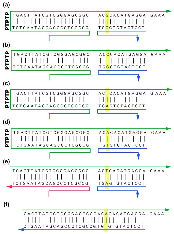
Figure 3. The Detailed Structures of the Signal-Generating Strands.

Panels (a)-(d) show the structures of the four different signal-generating strands when they are inserted into the origami. Arrowheads represent the 3′ ends of the strands. The target nucleotide pair is outlined in yellow, spanning the blue and green strands. The green strands contain a PTPTP unit on the left, where the ‘P’ represents a photo-cleavable linker. The 5′ end of the green strands is tightly hydrogen bonded to the M13 origami strand, as are the 3′ ends of the blue strands. Upon UV irradiation, the photo-cleavable linker is cut, leaving an arrangement such as the one shown in panel (e). Note that a 4-nucleotide toehold remains on the green strand. Panel (f) shows the structure of the competitive inhibitor used to equalize the displacement of the T symbol with the others.
