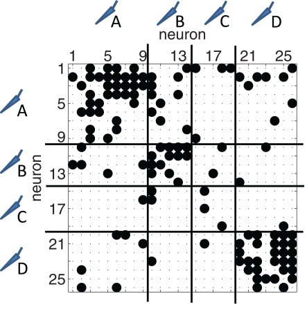
Figure 4.
Typical binary connectivity matrix from one reconstructed network with N = 26 neurons. A non-zero entry at row i and column j indicates a directed link from neuron i to neuron j. Neurons are sorted according to the electrode from which they were recorded from. In this example, four electrodes were used (A–D, the separation is indicated with the horizontal and vertical lines). Connections between neurons at the same electrode show up in blocks along the diagonal.

