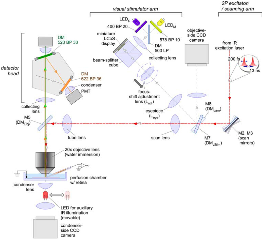
Fig. 2. Schematic overview of the Eyecup scope.
Drawing illustrating the different sections of the Eyecup scope; indicated are the optical paths for laser excitation light (entering from the top right; the source, a mode-locked Ti/Sapphire laser, is not shown) and the fluorescence light (emitted from the tissue in the chamber, bottom left). For details on the path of the stimulus light, see text and Fig. 5. LED light-emitting diode, LEDS short-wavelength, λpeak=400 nm, LEDM, middle-wavelength, λpeak=570 nm, PMT photo-multiplier tube, DM dichroic mirror [for specifications of DMObj (M5), DMvStim (M7) and DMCam (M8) see text], LCoS liquid crystal on silicon, IR infrared, BP band pass, LP long pass

