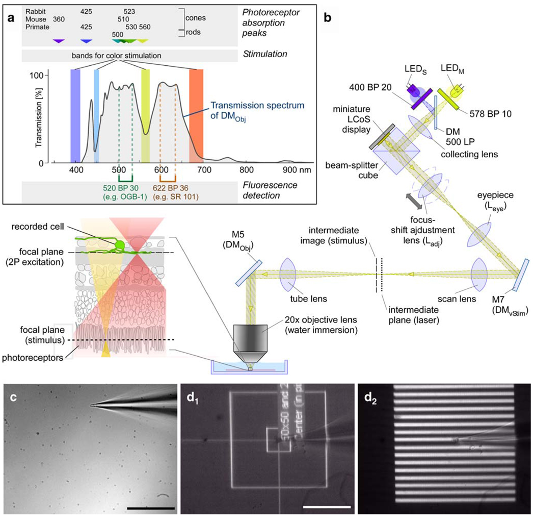
Fig. 5. Visual through-the-objective (TTO) stimulator and stimulation light path.
a Spectrum illustrating arrangement of fluorescent filters and dichroic mirror (DMObj) bands. Approximate photoreceptor absorption peaks in nm from [20, 21]. b Optical path of the stimulator light. The inset to the left of the objective lens shows the different focal planes within a schematic retinal cross-section (for abbreviations, see Fig. 2). c Picture taken with the objective-side CCD camera (see Fig. 2) through a 20× lens with IR illumination from below the chamber. A broken patch pipette touching the bottom of the recording chamber is visible. d Pictures taken through an oil condenser with the condenser-side CCD camera (Fig. 2) showing a patch electrode (same as in c) and different light patterns projected through the objective and focused onto the bottom of the recording chamber: a stimulus calibration pattern (d1; see “Stimulus alignment”) and a stripe pattern stimulus (d2; bright stripes, 8 µm=4 pixels wide) are shown. Scale bars: c, d 100 µm

