
Fig. 1.
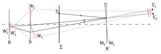
Schematic representation of the Michelson interferometry set up used for the Fizeau fringe projection technique. The schematic superimposes all branches onto the same axis for clarity. The ray shown coming from S will reflect off both mirrors such that the optical path difference of the reflected rays is only dependant on the thickness of the optical air wedge formed by the mirror, for small tilt angles α. In relation to Fig. 2, Σ represents the plane of the rotating diffuser, M2 is the common reference mirror and M1 the wavelength specific mirror. P and R are the pupil plane and retinal plane respectively, representing the eye. The plane containing the mirrors, R′, is conjugate to R.