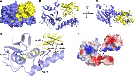
FIGURE 3.
Structure of the complex between ubiquitin and the ATXN3L Josephin domain. A, a space-filling model of the complex is shown; the Josephin domain is shown in blue, and ubiquitin in yellow. B, shown is a ribbon representation of the complex, shown in the same orientation as panel A. Helices 2, 3, 5, and 6 are labeled. C, an orthogonal view of the complex is shown. D, shown is a close-up showing the C terminus of the ubiquitin substrate threading into the ATXN3L active site and forming a covalent linkage with the cysteine nucleophile. Side chains are shown for the catalytic triad (Cys-14, His-119, and Asn-134) as well as for the three arginine-acid salt bridges that help to position the ubiquitin substrate. E, an exploded view of the complex shows the electrostatic potential surfaces of the two proteins and illustrates the charge complementarity between the helix 2/3 hairpin and the ubiquitin substrate. Figs. 3 and 5 were made using MacPyMOL (DeLano, W. L. (2008) The PyMOL Molecular Graphics System DeLano Scientific LLC, Palo Alto, CA).

