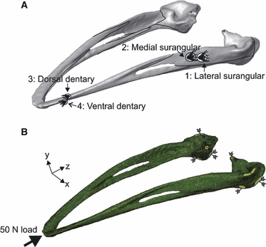
Fig. 1.

(A) Rendered model of the ostrich mandible (created from jaw 1 computed tomography scans) depicting the location of strain gauges. Black lines indicate sutural junctions. (B) Finite element mesh of jaw 1, illustrating the location and direction of constraints (green surface and converging arrows) and load (thick black arrow).
