Abstract
Susceptibility artifacts and B1+ inhomogeneity are major limitations in high field MRI. Parallel transmission methods are promising for reducing artifacts in high field applications. In particular, three-dimensional RF pulses have been shown to be useful for reducing B1+ inhomogeneity using multiple transmitters due to their ability to spatially shape the slice profile. Recently, two-dimensional spectral-spatial pulses have been demonstrated to be effective for reducing the signal loss susceptibility artifact by incorporating a frequency dependent through-plane phase correction. We present the use of four-dimensional spectral-spatial RF pulses for simultaneous B1+ and through-plane signal loss susceptibility artifact compensation. The method is demonstrated with simulations and in T2*-weighted human brain images at 3T using a four-channel parallel transmission system. Parallel transmission was used to reduce the in-plane excitation resolution to improve the slice-selection resolution between two different pulse designs. Both pulses were observed to improve B1+ homogeneity and reduce the signal loss artifact in multiple slice locations and several human volunteers.
Keywords: Four-dimensional RF pulses, spectral-spatial RF pulses, parallel transmission, susceptibility artifacts, B1+ inhomogeneity reduction
INTRODUCTION
High field MRI has many advantages including increased signal to noise ratio (1) and increased Blood Oxygen Level Dependent (BOLD) functional MRI (fMRI) contrast (2). Unfortunately, several confounds associated with the high field need to be addressed before many applications can reach their full potential. A major problem is image artifacts produced by inhomogeneity in the transmitted RF field (B1+) (3). The two factors that produce B1+ inhomogeneity at high field are the decreased RF wavelength, further shortened by the dielectric properties of tissue, and the attenuation of RF amplitude due to tissue conductivity (4). These artifacts appear as regions of increased and decreased brightness at 3T and even regions with no image magnitude at ultra high fields such as 7T. A second confound at high field are susceptibility artifacts that appear as distortions or as large voids in the images. They are particularly problematic in T2*-weighted imaging applications with long TE such as fMRI (5). The through-plane signal-loss artifact in axial slices is of primary importance due to the close proximity of air/tissue boundaries to the inferior brain areas. The fMRI data in many crucial regions such as the orbitofrontal cortex remain sub-optimal as a result.
Numerous methods have been proposed to mitigate B1+ inhomogeneity artifacts. These include specially designed coils (6), adiabatic pulses (7), image post-processing (8), and small-tip-angle tailored RF pulses (9). The tailored RF pulse technique has the advantage of being able to compensate for the B1+ inhomogeneity using a predetermined spatial excitation. More recently, it has been shown that “B1+ shimming” can be performed using multiple transmitters (10). Combining three-dimensional (3D) RF pulses with parallel transmission and sensitivity encoding (transmit SENSE) is currently showing great promise (11–13). The use of a parallel transmission has many additional benefits at high fields including managing the Specific Absorption Rate (SAR). Parallel transmission pulse designs have also been optimized for broad band excitations (14,15).
Numerous methods have been proposed to mitigate the signal loss artifact including z-shim methods (16), thin slice averaging (17), passive and active shim coils (18,19), and tailored RF pulses (20–22). All techniques have advantages and disadvantages; however, a desirable requirement is that the correction be performed in one shot. For example, multi-echo sequences or parallel transmission can be used to perform a single shot z-shim (23,24). Recently, the use of 2D spectral-spatial pulses has been shown to be very promising for compensating for the through-plane signal loss artifact using a single RF pulse (25,26). The basic idea is that regions needing the through-plane pre-compensatory phase will also tend to be off-resonance. The spectral-spatial pulse compensates the through-plane phase of the off-resonance spins and leaves the on-resonance spins unaffected.
We propose the use of four-dimensional (4D) spectral-spatial pulses for the simultaneous mitigation of B1+ inhomogeneity and through-plane susceptibility artifacts for high field T2*-weighted imaging. The method is presented using a dual-band design in a numerical framework that includes parallel transmission. The technique is demonstrated with simulations and human brain imaging experiments using a custom four-channel parallel transmission system. Reduction of excitation k-space using transmit SENSE was explored to trade in-plane resolution for an improved slice profile. Two pulse designs consisting of four 15 ms long 4D spectral-spatial pulses for a single parallel excitation are presented. Both sets of pulses were found to reduce B1+ inhomogeneity and signal loss artifact in several slice locations and several subjects.
THEORY
2D SPECTRAL-SPATIAL PULSES
The desired magnetization profile M(r, f) from an RF pulse B(t) can be determined for small tip angles (27) by
| [1] |
The equilibrium magnetization is given by M0, the pulse length by T, the frequency by f, and the excitation k-space by
| [2] |
Here the gyromagnetic ratio is given by γ = 2.675 × 10⁸ rad/s/T. A typical 2D spectral-spatial pulse consists of a train of N slice-select sub-pulses of length Tz each with a gradient Gz that alternates in sign for each sub-pulse. The k-space trajectory for each sub-pulse n can be written
| [3] |
The stop band is equal to the reciprocal of the length of each sub-pulse fs = 1/Tz. Typically a temporal weighting function of width Tw is applied on the overall composite pulse waveform such that the pass band is given approximately by fp = 1/Tw.
A 2D spectral-spatial pulse can be used for reducing the through-plane (z-direction) signal loss resulting from a magnetic susceptibility gradient along z that is assumed to be a function of frequency Gs(f). The pulse can be designed numerically using a target magnetization M(z,f) that has a slice profile P(z) and a pre-compensatory through-plane phase ϕ(z,f) = γGs(f)zTE:
| [4] |
Although the exact distribution of gradients over off resonance frequencies is likely complicated, it was shown in Ref. (26) that to good approximation a gradient that is a linear function of off resonance frequency works for many regions:
| [5] |
The slope of this gradient α can be determined by field map measurements or empirically through trial and error.
3D RF PULSES
A 3D RF pulse can be designed from the 2D spectral-spatial pulse by adding gradients that vary in x and y. A useful design is the so-called “fast-kz” trajectory created by adding x-y gradient blips between the slice-select sub-pulses to sample kx,y at discrete “rungs” along kz. Although the optimal rung placement depends on the application, for proof of concept, simple trajectories can be obtained by having a rung at the center kx,y = 0 as well as rungs at kx,y = ±Δk. For example, a five-rung trajectory can be written as
| [6] |
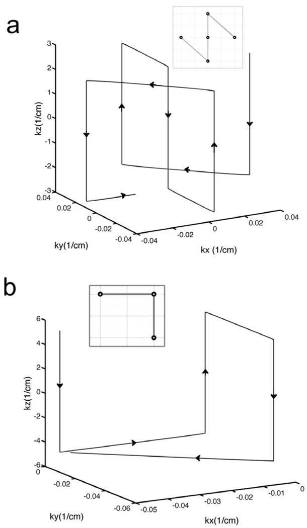
If the length of each slice-select sub-pulse is again Tz, the total length (ignoring a rewinder) is then 5 Tz. A three-rung trajectory can be obtained by using only the first three terms in the above trajectory. Figure 1 (a) and (b) shows diagrams of a five-rung and a three-rung k-space trajectory both with an x-y field of excitation FOX = 2π/Δk = 22 cm. 3D Pulses that reduce B1+ inhomogeneity can then be made from these trajectories using the small tip-angle equation including L transmitter sensitivities Cl(x, y) (28):
| [7] |
FIG. 1.
k-space trajectories used for each 3D sub-pulse in the 4D spectral-spatial RF pulses. (a) and (b) show “five-rung” and “three-rung” 3D trajectories for an in-plane (x-y) FOX = 2π/Δk = 22 cm. These 3D trajectories are repeatedly traversed in time to create spectral selectivity in the 4D pulse designs. The resolution along the slice-select (z) direction for the five-rung and three-rung trajectories was 1.0 and 1.7 mm, respectively.
This equation can be solved using standard least squares minimization routines such as the conjugate gradient technique.
4D SPECTRAL-SPATIAL PULSES
Repeating the 3D trajectory n =1,…,N times will produce a 4D spectral-spatial pulse trajectory. Each 3D pulse becomes a sub-pulse in the complete 4D spectral-spatial pulse. The five-rung sub-pulse trajectory can be written as
| [8] |
This is the same as above except the signs of the z-gradients change for each 3D RF sub-pulse. Keeping the first three terms can generate a three-rung sub-pulse trajectory. A five-rung 4D spectral-spatial pulse will have a frequency stop band fs = 1/5Tz and the three-rung 4D spectral-spatial pulse will have a frequency stop-band fs = 1/3Tz. The small tip angle equation for multiple transmitters can be extended to include frequency:
| [10] |
For computational simplicity, we will assume a dual-band design where the spins within the pass band at f1 = 0 need no through-plane phase pre-compensation and those at f2 = Δf require ϕ(z,Δf) = γGs(Δf)zTE. The desired magnetization profile is then
| [11] |
Further details of the pulse parameters are discussed below.
METHODS
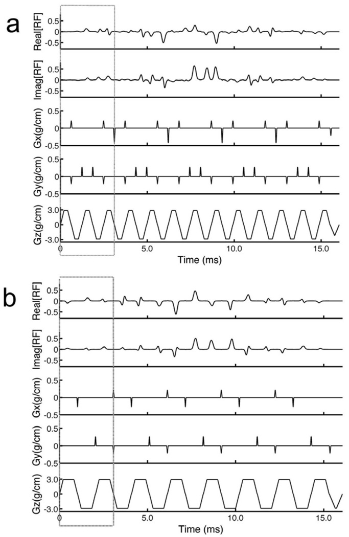
The 4D spectral-spatial pulses were designed using custom Matlab (The Mathworks, Natick, MA) programs. The peak gradient used in the algorithms was 3 G/cm and the peak slew rate was 18,000 G/cm/s. Two 4D spectral-spatial pulses were created using a five-rung and three-rung 3D sub-pulse, respectively, repeated N = 5 times. The choice for P(z) was a Gaussian with a half width of 5 mm (Gz = 3 G/cm) and the FOX was 22 cm for the in-plane direction. The length of the five-rung and three-rung 3D sub-pulses was fixed to 3.0 ms in both pulses by making the length of the individual slice-select pulses Tz = 0.6 and 1.0 ms, respectively. The longer length of the slice-select pulse in the three-rung design produced a greater excitation resolution along the z-direction of 1.0 mm compared to 1.7 mm for the five-rung design. This allowed for better sampling of the pre-compensatory phase for signal loss correction at the expense of B1+ inhomogeneity reduction due to the fewer rungs. The decreased number of rungs in the three-rung design, however, will be compensated using sensitivity encoding from the multiple transmitters. Both pulses had a total pulse length of 16.0 ms including a 1.0 ms long rewinder. The stop band for both pulses was fs = 333 Hz and a Gaussian temporal weighting was applied on the composite 4D spectral-spatial pulses such that the pass band was fp = 100 Hz. Signal loss phase pre-compensation parameters of Δf = 125 Hz and Gs = −0.01 G/cm were determined by post-hoc visual inspection of corrected brain images in preliminary experiments. These numbers give a value of α = −0.8 G/cm/Hz. Figure 2 (a) and (b) show the waveforms of the RF pulses and gradients for the five-rung and three-rung designs with the above parameters. The boxed regions show the individual 3D sub-pulses.
FIG. 2.
Diagrams of the 4D spectral-spatial RF pulses for one of four transmitters showing the real and imaginary parts of the RF waveforms as well as the waveforms for the x, y, and z gradients. (a) and (b) show 4D pulses constructed using the “five-rung” and “three-rung” 3D sub-pulse trajectories. The boxed regions in the pulse diagrams show the individual 3D sub-pulses. These pulses were used in all of the simulation and in-vivo experiments.
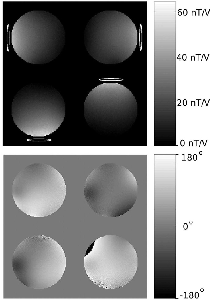
Complex maps of B1+ for each coil and B1- for all coils in a circularly polarized mode were obtained using the multi-angle method described in Ref. (29). Figure 3 shows images of the magnitude and phase of B1+ for the four transmit channels acquired in a single slice in a 20 cm spherical phantom. For proof of concept purposes, these maps from the phantom were used as approximate B1+ maps in all of the in vivo studies. This assumption was found to work well in preliminary experiments for a range of 8–10 human brain slices centered at the same location in the coil as the phantom maps. This greatly eased the implementation of the pulses because the B1+ mapping does not need to be performed in every subject at every slice location. In this manner, only one set of five-rung and three-rung pulses needed to be constructed and saved on the scanner. The B1- maps were used during image reconstruction to remove any receiver B1- inhomogeneity.
FIG. 3.
Transmitter sensitivity maps showing the (a) magnitude and (b) phase of the B1+ profile. These maps were acquired in a 20 cm diameter spherical phantom with dielectric properties similar to the human brain. All of the pulses were designed using these B1+ maps. Maps of the B1− (not shown) were acquired as well and used during image reconstruction to remove receiver inhomogeneity.
Bloch equation simulations as well as human brain imaging experiments were performed to validate the pulse designs. The imaging experiments were performed on a TIM Trio 3T whole body scanner (Siemens Medical Systems, Erlangen, Germany). A standard 2D FLASH sequence for spoiled gradient echo imaging was used for the experiments (30/500 ms TE/TR, 30° flip angle, eight 5 mm thick slices, 1 mm slice gap, 22 cm FOV, 128 × 128 matrix size, 1:04 scan time). Parallel transmission was achieved using a custom RF transmission system that consisted of a four transmitter Tecmag Apollo NMR console (Tecmag Inc., Houston, TX) with four 300 W amplifiers and a customized four-channel transmit-receive head coil (30). The head coil was mounted on a cylinder approximately 30 cm long and 30 cm diameter and consisted of four 8 cm by 17 cm loops. The Tecmag console is capable of transmitting four unique phase- and frequency-synchronized complex RF waveforms that could be programmed using the Tecmag NTNMR pulse sequence software and triggered by the Siemens scanner. All of the RF waveforms were stored on the Tecmag console. The Siemens console was used to generate all gradients, acquire data, and reconstruct images using the FLASH sequence and related software. Both consoles were synchronized using the Siemens scanner’s 10 MHz clock.
The human brain data were obtained on five healthy adult humans scanned after informed consent approved by the University of Hawaii and Queens Medical Center joint IRB. The general protocol was to first apply a three-plane localizer to align the eight gradient echo axial slices around the sinus region. The pre-scan routine was run using the Siemens scanner alone with an identical RF pulse played out on its single transmitter attached to one of the coils. The pre-scan information including flip angle (a 30° flip angle corresponded to a coil voltage of approximately 30 V), center frequency, and slice offsets were passed from the Siemens scanner to the Tecmag NTNMR sequence using a customized Visual Basic program. The SAR was monitored in separate experiments using the Siemens scanner running the FLASH sequence with its single RF transmitter attached to one of the coils as well as split to all coils. It was found that the SAR was always well below the safety threshold. Three sets of images were then acquired. The first set was acquired with a standard Gaussian 1D slice-select pulse of shape P(z) to serve as the control images. This pulse was applied simultaneously on all four channels with successive phase increments of 90° degrees to ensure a circularly polarized excitation. The other two sets were acquired using the five-rung and three-rung 4D spectral-spatial pulses, respectively.
RESULTS
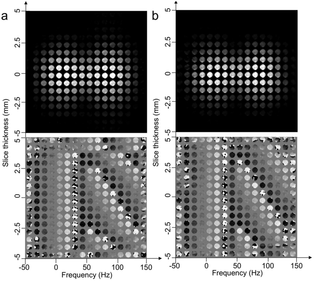
Figure 4 shows Bloch equation simulations of the magnitude and phase of the 4D magnetization excited by the (a) five-rung and (b) three-rung 4D spectral-spatial pulses. The simulations required the use of the sensitivity maps shown in Figure 3. The images are displayed as individual images in x-y distributed along the slice-select (z) and frequency (f) directions. Excellent agreement between the above pulse design parameters and simulated results is seen. In particular, note that two magnitude bands appear in both (a) and (b) centered at 0 and 125 Hz. The band at 0 Hz has no through-plane pre-compensatory phase whereas the band at 125 Hz has a linear phase of approximately 2π radians across the slice as desired.
FIG. 4.
(a) and (b) show Bloch equation simulations of the magnitude and phase of the 4D magnetization produced by the pulses shown in Fig. 2 (a) and (b) for four transmitters. The sensitivity maps in Fig. 3 were also used in the simulations. Each simulation figure shows the magnetization in x-y as functions of the slice-select z and the frequency f directions. Note that two frequency bands, one at 0 Hz and a second at 125 Hz, can be seen in the simulation and that the slice thickness is 5 mm. The magnetization at 125 Hz has a linear phase along the slice-select direction to compensate for the through-plane susceptibility gradient.
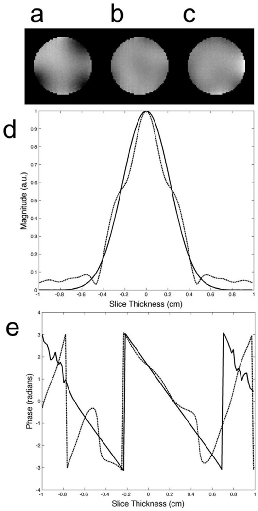
Figure 5 shows higher resolution simulations of the x-y magnetization centered at f and z both equal to 0. Figure 5 (a) shows the magnetization from the circularly polarized 1D Gaussian slice-select pulses. Note the loss of image magnitude in the regions near the edges where the sensitivities overlap. This is a result of phase cancellation when the complex sensitivities are added together. Figure 5 (b) and (c) show the x-y magnetization from the five-rung and three-rung 4D spectral-spatial pulses. Note that the slice-profile in both is improved over that in (a). The standard deviations for (a–c) are 0.037, 0.019, and 0.020 respectively. The slice profiles along z at f = 125 Hz from both 4D spectral-spatial pulses are shown in Fig. 5 (d). The dashed and solid lines show the profiles for the five-rung and three-rung pulses, respectively. The slice-profile for the three-rung pulse is identical to P(z) however the five-rung pulse is slightly distorted. This is a result of the lower resolution along z (1.7 mm compared to 1.0 mm) being less able to support the desired through-plane phase correction across the 5 mm thick slice width.
FIG. 5.
Bloch equation simulations of the magnitude of the x-y magnetization at 0 Hz excited by all four transmitters using (a) a standard circularly-polarized 1D pulse and the (b) five-rung and (c) three-rung 4D spectral-spatial pulses shown in Fig 2 (a) and (b). Note the improved in-plane B1+ uniformity using the 4D spectral-spatial pulses in both (b) and (c). (d) Plots of the simulated magnitude at 125 Hz along z obtained using the five-rung and three-rung pulses displayed as dotted and solid lines respectively. (e) Plots of the simulated phase at 125 Hz along z obtained using the five-rung and three-rung pulses displayed as dotted and solid lines respectively. The three-rung pulse produces a more accurate magnitude and phase due to a higher slice-select resolution.
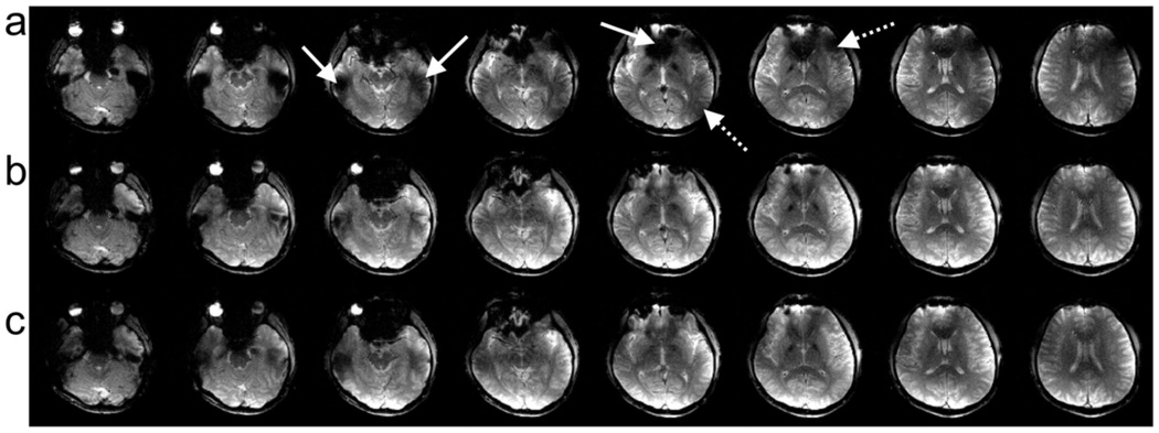
Figure 6 shows eight brain slices from one of the five subjects scanned at 3T using the gradient echo sequence with a 30 ms TE. The top row (a) shows images excited using the circularly polarized 1D slice-select pulses. The solid and dotted arrows indicate regions where there is signal loss and B1+ inhomogeneity, respectively. The signal loss artifact is seen in regions near air cavities in the brain as expected. The B1+ inhomogeneity appears as regions of decreased image magnitude due to uneven transmission sensitivity or where there is phase cancellation in regions of overlapping sensitivity as seen in the simulations. Note that these artifacts appear in all slices. The middle row (b) and the bottom row (c) show the same set of slices excited using the five-rung and three-rung 4D spectral-spatial pulses, respectively. Note the recovery of signal loss and improved B1+ homogeneity in all slices. Similar results were seen in the other four subjects.
FIG. 6.
This figure shows brain slices from a representative subject. (a) Images excited using the circularly polarized 1D slice-select pulses from each of the four transmitters. The solid and dotted arrows indicate regions where there is signal loss and B1+ inhomogeneity, respectively. (b, c) show the same set of slices excited using the five-rung and three-rung 4D spectral-spatial pulses, respectively. Note the recovery of signal loss and improved B1+ homogeneity in all slices. Similar results were seen in all subjects.
Table 1 shows the comparison of results across all subjects. Two regions of interest (ROI’s) were taken in the sinus region in two slices in all subjects where signal loss occurred due to magnetic susceptibility variations. The recovery percentage of pixels with magnitude below 20% of the normalized ROI maximum from the standard 1D pulse was chosen as an indication of susceptibility artifact correction. In this manner, pixels outside of the artifact-affected region in the ROI were excluded. The average percent signal recovery was 91.9 and 88.2 with p-values of 9.9×10⁻⁵ and 8.0×10⁻⁵ for the five-rung and three-rung pulses, respectively. The coefficient of variance across the whole brain was selected as an indication of B1+ homogeneity. The average percent decrease in variance was 22.6 and 22.4 with p-values of 0.4×10⁻² and 1.5×10⁻² for the five-rung and three-rung pulses respectively.
Table 1.
This table lists the percent improvement in signal loss recovery and B1+ homogeneity for the five-rung and three-rung 4D spectral-spatial pulses over the standard pulse (averaged across all ROI’s for all slices in each subject). The p-values reflect the significance of the results compared to the standard pulse.
| % Signal Loss Recovery | |||||||
|---|---|---|---|---|---|---|---|
| Subject # | 1 | 2 | 3 | 4 | 5 | Average | p-Value |
| Five-Rung | 94.1 | 77.9 | 92.7 | 98.2 | 96.6 | 91.9 | 9.9×10⁻⁵ |
| Three-Rung | 98.3 | 58.4 | 90.8 | 96.9 | 96.5 | 88.2 | 8.0×10⁻⁵ |
| % B1+ Homogeneity Improvement | |||||||
| Subject # | 1 | 2 | 3 | 4 | 5 | Average | p-Value |
| Five-Rung | 25.1 | 22.6 | 9.8 | 20.7 | 34.8 | 22.6 | 0.5×10⁻² |
| Three-Rung | 28.9 | 19.1 | 5.9 | 19.1 | 39.1 | 22.4 | 1.6×10⁻² |
DISCUSSION
We have demonstrated that a 4D spectral-spatial pulse can be used to simultaneously reduce the through-plane signal loss artifact as well as B1+ inhomogeneity. The improvement in B1+ homogeneity can be seen very clearly in Fig. 6 and Table 1 for all slices and subjects. Both pulse designs performed similarly. In particular, large improvements are seen in the regions between adjacent transmitters where there are phase cancellations. Correction of these regions is not possible using standard B1+ shimming techniques with multiple transmitters and 1D pulses. One assumption used in the pulse design was that the B1+ maps acquired from a single slice in a spherical phantom would be adequate. We found that this assumption held very well in the in vivo brain scans. This greatly eased the pulse implementation because only one set of pulses was needed for all subjects and slice locations. Furthermore, the pulses could then be designed off line without valuable time being lost with a subject in the scanner. It is unclear if such an assumption would always hold for all coils, slice locations, and higher field strengths such as 7T. One would expect a more improved B1+ uniformity using in vivo maps acquired for each subject at each slice location. In general, the need for a rapid B1+ mapping technique and on-line pulse design remains a challenge for parallel transmission methods.
Figure 6 and Table 1 show that both pulse designs are successful at recovering the susceptibility induced signal loss. We found that a value of Gs = −0.01 G/cm centered at a single off-resonance frequency Δf = 125 Hz worked well for recovering the majority of the signal loss in all slices and in all subjects. In particular, the sinus and auditory regions showed large improvements in all subjects. This assumption along with the robustness to B1+ mapping discussed above implies that it is possible to use one set of prefabricated pulses in most subjects and get significant improvements. It was noticed, however, that some brain regions were slightly under or over compensated or even not corrected. One reason may be because the values for Gs and Δf were determined by post-hoc visual inspection of corrected images. Adding more frequency bands may help address this. The actual range of gradient values and their distribution over frequency, however, remains an important unanswered question. We are currently working on methods that directly measure the through plane Gs as a function of frequency as well as exploring the idea of using pulses with different frequency characteristics on each transmitter channel. We are also planning on implementing the pulses at 7T where we expect shorter pulse lengths than needed at 3T due to the larger frequency separation Δf. The amount of through-plane phase compensation, however, should be the same as at 3T due to the shorter TE at 7T.
Parallel transmission methods were used to reduce the number of rungs of the 3D sub-pulses to improve the slice-selection resolution. The three-rung design had a 1.0 mm excitation resolution along the slice-select direction compared to 1.7 mm resolution of the five-rung pulse. The higher resolution allows for a finer sampling of the through-plane phase correction. The simulated results in Fig. 5 show that a more accurate slice profile was obtained at the frequency where the phase correction is required. Table 1 shows no statistical difference between the two pulses for the recovery of lost signal; however, visual inspection (for example the second and third slices in Fig. 6 (b) and (c)) indicates that the three-rung design provides a cleaner correction of the signal loss artifact. Alternatively, reducing the number of rungs could be used to create shorter sub-pulses if a larger stop band is desired.
We expected the five-rung pulse to provide a slightly better B1+ inhomogeneity reduction than the three-rung pulse because the five rungs provide a more symmetric sampling in kx-ky than the three rungs. However, no visual or statistical differences between pulses were observed. This is most likely because the reduction in kx-ky sampling with only three rungs is offset with the use of sensitivity encoding and multiple transmitters. The five-rung design was found (data not shown) to provide comparable signal loss and B1+ homogeneity improvements using the body coil’s single transmitter. The three-rung pulse, however, performed poorly with a single transmitter. Parallel transmission should be more favorable for the five-rung pulse at higher fields such as 7T.
CONCLUSIONS
We have presented the use of a 4D spectral-spatial pulse to simultaneously reduce the through-plane signal loss artifact from susceptibility variations as well as B1+ inhomogeneity at 3T in T2* weighted human brain imaging. Both a five-rung and a three-rung implementation were demonstrated using only two frequency bands. The three-rung design exploited the use of transmit sensitivity encoding to improve the slice-selection profile with no significant decrease in B1+ homogeneity. A single set of pulses from either implementation was shown to be successful for several subjects and several slice locations.
Acknowledgments
Work supported by the National Institute on Drug Abuse (R01DA019912, K02DA020569). Core resources supported by the National Center for Research Resources (G12-RR003061, P20-RR011091), National Institute of Neurological Disorders and Stroke (U54-NS56883), and the Office of National Drug Control Policy
References
- 1.Edelstein WA, Glover GH, Hardy CJ, Redington RW. The intrinsic signal-to-noise ratio in NMR imaging. Magn Reson Med. 1986;3(4):604–618. doi: 10.1002/mrm.1910030413. [DOI] [PubMed] [Google Scholar]
- 2.Ogawa S, Lee T, Nayak A, Glynn P. Oxygenation-sensitive contrast in magnetic resonance image of rodent brain at high magnetic fields. Magn Reson Med. 1990;14:68–78. doi: 10.1002/mrm.1910140108. [DOI] [PubMed] [Google Scholar]
- 3.Glover GH, Hayes CE, Pelc NJ, Edelstein WA, Mueller OM, Hart HR, Hardy CJ, O'Donnell M, Barber WD. Comparison of linear and circular polarization for magnetic resonance imaging. J Magn Reson. 1985;64:255–270. [Google Scholar]
- 4.Yang QX, Wang J, Zhang X, Collins CM, Smith MB, Liu H, Zhu XH, Vaughan JT, Ugurbil K, Chen W. Analysis of wave behavior in lossy dielectric samples at high field. Magn Reson Med. 2002;47(5):982–989. doi: 10.1002/mrm.10137. [DOI] [PubMed] [Google Scholar]
- 5.Haacke E, Tkach J, Parrish T. Reduction of T2* dephasing in gradient field-echo imaging. Radiology. 1989;170:457–462. doi: 10.1148/radiology.170.2.2911669. [DOI] [PubMed] [Google Scholar]
- 6.Alsop D, Connick T, Mizsei G. A spiral volume coil for improved RF field homogeneity at high static magnetic field strength. Magn Reson Med. 1998;40:49–54. doi: 10.1002/mrm.1910400107. [DOI] [PubMed] [Google Scholar]
- 7.Staewen R, Johnson A, Ross B, Parrish T, Merkle H, Garwood M. 3-D FLASH imaging using a single surface coil and a new adiabatic pulse, BIR-4. Invest Radiol. 1990;25:559–567. doi: 10.1097/00004424-199005000-00015. [DOI] [PubMed] [Google Scholar]
- 8.Cohen MS, DuBois RM, Zeineh MM. Rapid and effective correction of RF inhomogeneity for high field magnetic resonance imaging. Hum Brain Mapp. 2000;10(4):204–211. doi: 10.1002/1097-0193(200008)10:4<204::AID-HBM60>3.0.CO;2-2. [DOI] [PMC free article] [PubMed] [Google Scholar]
- 9.Saekho S, Yip C-P, Noll DC, Boada FE, Stenger VA. A Fast-kz 3D Tailored RF Pulse for Reduced B1 Inhomogeneity. Magn Reson Med. 2006;55:719–724. doi: 10.1002/mrm.20840. [DOI] [PMC free article] [PubMed] [Google Scholar]
- 10.Collins CM, Liu W, Swift BJ, Smith MB. Combination of optimized transmit arrays and some receive array reconstruction methods can yield homogeneous images at very high frequencies. Magn Reson Med. 2005;54(6):1327–1332. doi: 10.1002/mrm.20729. [DOI] [PubMed] [Google Scholar]
- 11.Zhu Y. Parallel excitation with an array of transmit coils. Magn Reson Med. 2004;51(4):775–784. doi: 10.1002/mrm.20011. [DOI] [PubMed] [Google Scholar]
- 12.Katscher U, Bornert P, Leussler C, van den Brink J. Transmit SENSE. Magn Reson Med. 2003;49(1):144–150. doi: 10.1002/mrm.10353. [DOI] [PubMed] [Google Scholar]
- 13.Zhang Z, Yip CY, Grissom W, Noll DC, Boada FE, Stenger VA. Reduction of transmitter B1 inhomogeneity with transmit SENSE slice-select pulses. Magn Reson Med. 2007;57(5):842–847. doi: 10.1002/mrm.21221. [DOI] [PMC free article] [PubMed] [Google Scholar]
- 14.Setsompop K, Wald LL, Alagappan V, Gagoski BA, Adalsteinsson E. Magnitude least squares optimization for parallel radio frequency excitation design demonstrated at 7 Tesla with eight channels. Magn Reson Med. 2008;59(4):908–915. doi: 10.1002/mrm.21513. [DOI] [PMC free article] [PubMed] [Google Scholar]
- 15.Kerr A, Etezadi-Amoli M, Fautz H-P, Vogel M, Gross P, Zhu Y, Pauly J. Dual-band RF shimming at high-field with parallel excitaiton. Proceedings of the 16th Annual Meeting of ISMRM; Toronto, Canada. 2008. (Abstract 617). [Google Scholar]
- 16.Constable R. Functional MR imaging using gradient-echo echo-planar imaging in the presence of large static field inhomogeneities. J Magn Reson Imag. 1995;5(6):746–752. doi: 10.1002/jmri.1880050622. [DOI] [PubMed] [Google Scholar]
- 17.Merboldt K-D, Finsterbusch J, Frahm J. Reducing inhomogeneity artifacts in functional MRI of human brain activation-thin slices vs gradient compensation. J Magn Reson. 2000;145:184–191. doi: 10.1006/jmre.2000.2105. [DOI] [PubMed] [Google Scholar]
- 18.Wilson JL, Jezzard P. Utilization of an intra-oral diamagnetic passive shim in functional MRI of the inferior frontal cortex. Magn Reson Med. 2003;50(5):1089–1094. doi: 10.1002/mrm.10626. [DOI] [PubMed] [Google Scholar]
- 19.Hsu JJ, Glover GH. Mitigation of susceptibility-induced signal loss in neuroimaging using localized shim coils. Magn Reson Med. 2005;53(2):243–248. doi: 10.1002/mrm.20365. [DOI] [PubMed] [Google Scholar]
- 20.Cho Z, Ro Y. Reduction of susceptibility artifact in gradient-echo imaging. Magn Reson Med. 1992;23:193–200. doi: 10.1002/mrm.1910230120. [DOI] [PubMed] [Google Scholar]
- 21.Stenger VA, Boada FE, Noll DC. Three-dimensional tailored RF pulses for the reduction of susceptibility artifacts in T2*-weighted functional MRI. Magn Reson Med. 2000;44:525–531. doi: 10.1002/1522-2594(200010)44:4<525::aid-mrm5>3.0.co;2-l. [DOI] [PMC free article] [PubMed] [Google Scholar]
- 22.Yip CY, Fessler JA, Noll DC. Advanced three-dimensional tailored RF pulse for signal recovery in T2*-weighted functional magnetic resonance imaging. Magn Reson Med. 2006;56(5):1050–1059. doi: 10.1002/mrm.21048. [DOI] [PubMed] [Google Scholar]
- 23.Song AW. Single-Shot EPI with Signal Recovery from the Susceptibility-Induced Losses. Magnetic Resonance in Medicine. 2001;46:407–411. doi: 10.1002/mrm.1205. [DOI] [PubMed] [Google Scholar]
- 24.Deng W, Yang C, Alagappan V, Wald LL, Boada FE, Stenger VA. Simultaneous Z-Shim Method for Reducing Susceptibility Artifacts with Multiple Transmitter. Magentic Resonance in Medicine. 2009;61:255–259. doi: 10.1002/mrm.21870. [DOI] [PMC free article] [PubMed] [Google Scholar]
- 25.Meyer CH, Pauly JM, Macovski A, Nishmura DG. Simultaneous spatial and spectral selective excitation. Magn Reson Med. 1990;15:287–304. doi: 10.1002/mrm.1910150211. [DOI] [PubMed] [Google Scholar]
- 26.Yip CY, Yoon D, Olafsson V, Lee S, Grissom WA, Fessler JA, Noll DC. Spectral-spatial pulse design for through-plane phase precompensatory slice selection in T(2) (*)- weighted functional MRI. Magn Reson Med. 2009;61(5):1137–1147. doi: 10.1002/mrm.21938. [DOI] [PMC free article] [PubMed] [Google Scholar]
- 27.Pauly JM, Nishimura D, Macovski A. A k-space analysis of small-tip-angle excitation. J Magn Reson. 1989;81:43–56. doi: 10.1016/j.jmr.2011.09.023. [DOI] [PubMed] [Google Scholar]
- 28.Grissom W, Yip CY, Zhang Z, Stenger VA, Fessler JA, Noll DC. Spatial domain method for the design of RF pulses in multicoil parallel excitation. Magn Reson Med. 2006;56(3):620–629. doi: 10.1002/mrm.20978. [DOI] [PubMed] [Google Scholar]
- 29.Setsompop K, Alagappan V, Gagoski BA, Potthast A, Hebrank F, Fontius U, Schmitt F, Wald LL, Adalsteinsson E. Broadband slab selection with B1+ mitigation at 7T via parallel spectral-spatial excitation. Magn Reson Med. 2009;61(2):493–500. doi: 10.1002/mrm.21834. [DOI] [PMC free article] [PubMed] [Google Scholar]
- 30.Alagappan V, Nistler J, Adalsteinsson E, Setsompop K, Fontius U, Zelinski A, Vester M, Wiggins GC, Hebrank F, Renz W, Schmitt F, Wald LL. Degenerate mode band-pass birdcage coil for accelerated parallel excitation. Magn Reson Med. 2007;57(6):1148–1158. doi: 10.1002/mrm.21247. [DOI] [PubMed] [Google Scholar]


