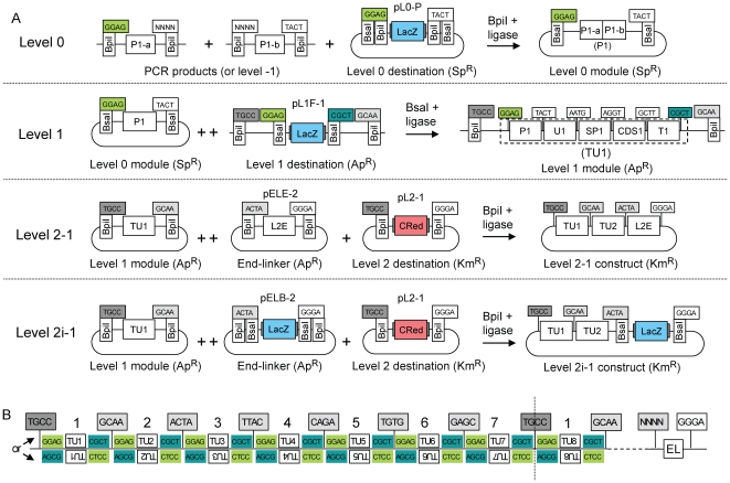
Figure 4. Modular cloning strategy.
(A) Constructs are assembled by mixing in one tube all module plasmids (or PCR fragments for level 0) and a destination vector together with the appropriate type IIS enzyme (indicated above the arrows) and ligase. ++ indicates that only one of several modules was drawn due to space limitation. Each fusion site is shown as a box indicating its 4 nucleotides; the two boxes below show which type IIS recognition sites flank the fusion sites on the left and/or right sides. P1-a/b, promoter fragment a or b; U, 5′ untranslated region; SP, signal peptide; CDS, coding sequence; T, terminator; CRed, red color selectable marker; LacZ, lacZα fragment, blue color selectable marker; L2E, end-linker 2; ApR, ampicillin resistance; KmR, kanamycin resistance; SpR, spectinomycin resistance. (B) General structure of level 2 constructs. Transcription units are located between the sequences GGAG and CGCT (remnants of fusion sites used for assembly of transcription units in forward orientation) or AGCG and CTCC (for transcription units cloned in reverse orientation). The number above the transcription units indicates the relative position of the transcription units in the final construct (indicates which of the 7 level 1 destination vectors shown in figure 5 was used for assembly of this transcription unit). The construct is terminated at the right end by an end-linker (EL) that joins the downstream fusion site of the last transcription unit (NNNN) with the downstream fusion site of the destination vector (GGGA).

