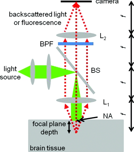
Figure 1.
Schematic diagram of a camera-based optical imaging system. A collimated light beam illuminates the brain tissue. For absorption imaging, the backscattered light (marked by arrows) is collected by lens L1 and imaged onto a two dimensional detector plane by lens L2. For fluorescence imaging, a BPF is inserted in front of the camera allowing the detection of the fluorescence. The system is arranged in a 4f configuration. f: focal length of L1 and L2. BS: beamsplitter. NA: numerical aperture.

