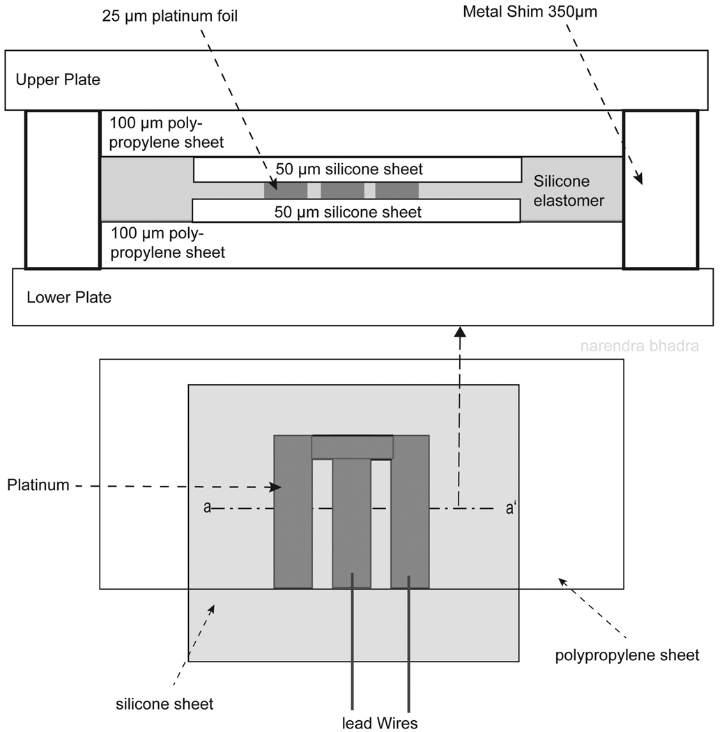
Figure 2.
Cross sectional illustration of the layers of electrode materials in the molding plates. The first layer on the lower plate was a piece of 100 µm polypropylene, followed by a layer of 50 µm silicone sheeting. The platinum array was placed between the two layers of silicone sheeting, followed by a second piece of polypropylene. The polypropylene was used to add thickness to the electrode materials (thickness of 125 µm) so equal pressure could be applied across the surface of the electrode while in the laminating press without damaging the thicker insulated lead wire (thickness of 250 – 350 µm). Metal shims were placed in the corners of the metal plates to maintain the final desired electrode thickness and limit compression of the electrode materials while in the laminating press.

