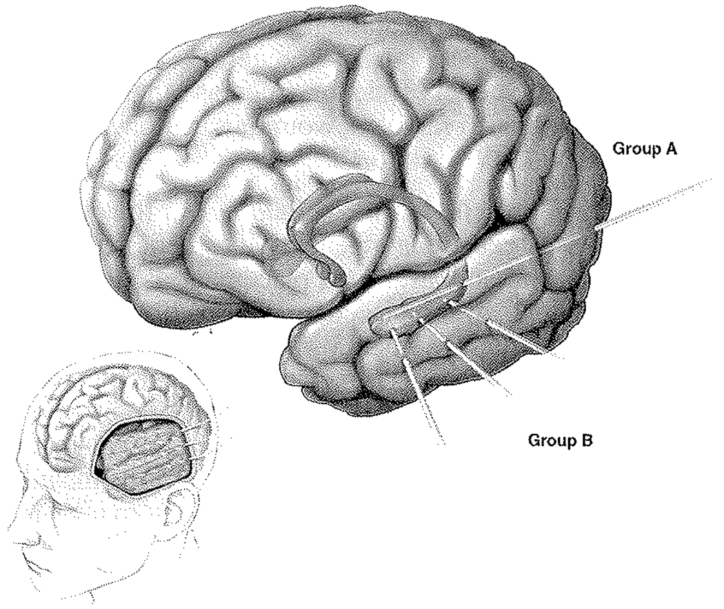
FIG. 1.
Graphic illustration of depth electrode insertion. Computerized lateral view of the left cerebral hemisphere (lower left) shows typical exposure and grid placement for temporal and frontal lobe coverage. Larger cerebrum in isolation (upper right) shows a shadow illustration of the deep amygdala and hippocampus. The 2 different techniques are illustrated: Group A, consisting of the typical occipital insertion and longitudinal depth electrode coverage of the hippocampus; and Group B, composed of the orthogonally directed depth electrodes typically inserted through the grid.

