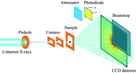
Figure 1.
Schematic layout of the X-ray diffraction microscope. A 20 µm pinhole and two guard corners are used to define a clean X-ray beam. The oversampled diffraction pattern is measured by a CCD camera with 1340 × 1300 pixels and a pixel size of 20 µm × 20 µm. A beamstop is used to block the direct beam for protecting the detector and to avoid pixel saturation near the beamstop which would result in severely smeared patterns. An attenuator and a photodiode are used to align the microscope to the X-rays.

