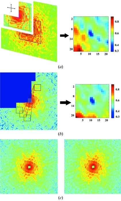
Figure 4.
(a) Merging of the LROI and HROI diffraction patterns. An overlapping region (i.e. the boot-shaped region) is used to align the LROI and HROI patterns by minimizing the error distribution map (right). (b) Localization of the centre pixel of the diffraction pattern by using centrosymmetry. The error distribution map (right) indicates the optimal centre pixel. (c) A complete diffraction pattern after the missing quadrant is recovered by using centrosymmetry (left). The first and third quadrant data are averaged to enhance the signal-to-noise ratio of the diffraction pattern (right).

