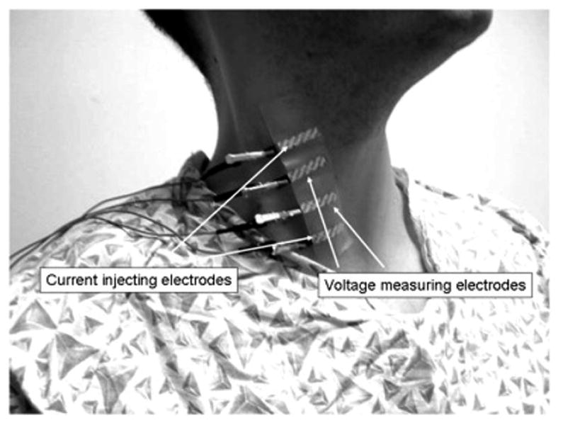
Figure 1. Measurement setup.

Electrical impedance myography being performed on right sternocleidomastoid. The two outer electrodes inject the electrical current; the two inner electrodes measure the resulting voltages, from which the impedance values are calculated.
