
Fig. 1.
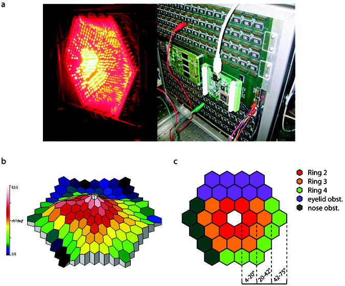
The mf-ERG hardware, example mf-ERG response profile, and analysis of concentric rings representing different retinal eccentricities. (a) The stimulator was designed and constructed out of specially shaped circuit boards so that when placed edge-to-edge created a geodesic dome. Super bright LEDs were then aimed to a focal point and cyclic summation was used to extract topographical regions. The 650 nm LEDs were on in the photograph. (b) A typical mf-ERG response profile obtained from the device. (c) To compare different retinal eccentricities, ERG amplitudes were averaged from “rings” of increasing eccentricity. Analysis was complicated by the fact that the nose and upper brow obstructed the light entering the eye to a variable extent in different subjects. Unreliable data between trials and subjects were commonly found in these areas. To maintain reliability of collected data, only areas labeled in red, orange, and green were used in the ring averages.