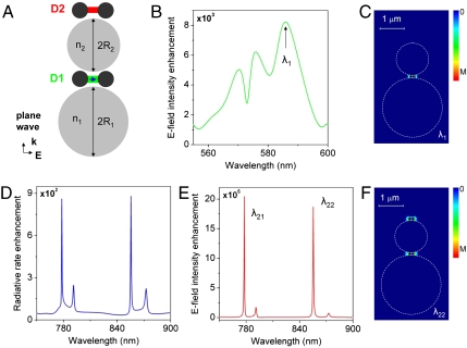
Fig. 2.
Light in-coupling, frequency conversion, and multiplexing in optoplasmonic circuits. (A) A schematic of the optoplasmonic multiplexer (R1 = 1.2 μm, n1 = 1.45, R2 = 0.65 μm, n2 = 2.4, r = 55 nm, w = 20 nm, h = 60 nm). (B) Enhancement (over the free-space value) of the electric field intensity detected at D1 under the plane wave excitation. (C) Electric field intensity distribution (linear scale) in the multiplexer at λ1 = 585 nm under the plane wave illumination. (D) Radiative rate enhancement of the dipole at D1 as a function of wavelength. (E) Electric field intensity enhancement detected at D2 under the excitation by the emitting dipole at D1 as a function of wavelength. (F) Electric field intensity distribution (linear scale) in the multiplexer at λ22 = 855.5 nm under the illumination by the emitting dipole at D1.

