Figure 5.
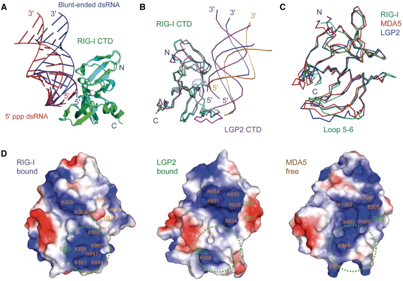
RIG-I and LGP2 CTDs bind blunt-ended dsRNA and 5′ ppp dsRNA differently. (A) Superposition of RIG-I CTD bound to the 14-bp blunt-ended dsRNA and a 14-bp 5′ ppp dsRNA with the same sequence. RIG-I CTDs bound to the blunt-ended dsRNA (blue) and the 5′ ppp dsRNA (red) are shown by the green and cyan ribbons, respectively. (B) Superposition of RIG-CTD bound to the blunt-ended dsRNA and the 5′ ppp dsRNA and LGP2 CTD bound to blunt-ended dsRNA. The blunt-ended dsRNA bound to RIG-I CTD is shown by the blue ribbons. The 5′ ppp dsRNA bound to RIG-I CTD is shown by the orange ribbons. A 14-bp dsRNA (magenta ribbons) is superimposed on the 8-bp dsRNA in the LGP2 CTD:dsRNA complex structure to facilitate comparisons. (C) Superposition of RIG-I (ligand bound), MDA5 (ligand free) and LGP2 (ligand bound) CTD structures. The RNA-binding surfaces of the proteins face the reader. (D) Electrostatics of the RNA-binding surfaces of the RLR CTDs. Positively charged surfaces are colored blue and negatively charged surfaces are red. The ppp-binding site of RIG-I CTD and corresponding regions of LGP2 and MDA5 are indicated by the green circles. Key residues involved in RNA-binding are labeled. Residues of RIG-I CTD interacting with the complementary strand of the dsRNA and corresponding residues in MDA5 and LGP2 CTDs are underlined.

