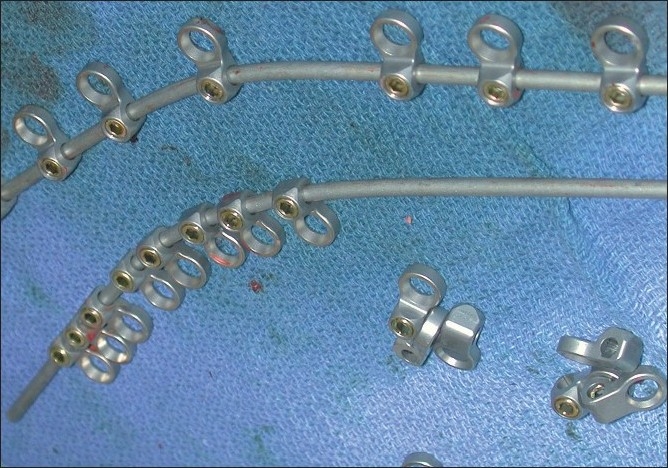
Figure 5.

This photograph demonstrates the application of the eyelets on the rods prior to positioning and placement. Utilizing the rod bender, two similarly configured, mirror-image rods have eyelets applied opposite the retained spinous processes. The rods are then applied dorsally, with the eyelets affixed ventrally. This is followed by passage of a braided titanium cable through the base of the spinous processes; each side of the wire is then brought up through the eyelets and then tightened in a cerclage fashion over the dorsal/superficial rods.
