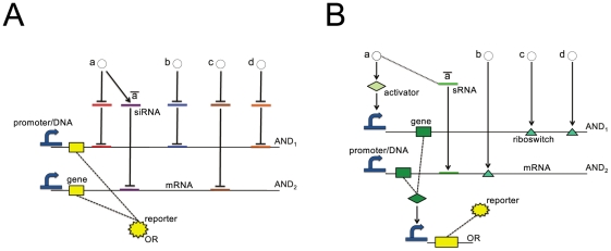
Figure 5. Comparison of a RNAi-based with an automatically designed circuit.
The Boolean formula  is here represented both (A) as the circuit provided by Rinaudo et al.
[23] with
  different siRNAs and (B) as one of the
  solutions computed by our tool, using two activators and one sRNA. Notice that
  and
and  correspond to
  and
and  , respectively. Dashed lines indicate either protein synthesis or input signal conversion into a regulatory factor (NOT operation). For a better comparison with Rinaudo's scheme, we do not include the input layer in (B).

