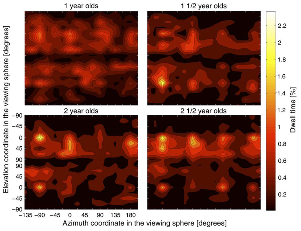
Figure 4.
Dwell time map across all objects for the four age groups in Experiment 1. Figure 1’s right panel depicts the coordinate system used to define object orientation with respect to the line of sigh. Each map is shown with the elevation axis duplicated; the top half corresponds to the object in an upright orientation and the bottom half shows the reverse. The order of the elevation values in this axis is arranged so that the object view is symmetrical about the map’s horizontal mid-line. The azimuth and elevation coordinates for the six planar views are as follows: +90° elevation, top; −90° elevation, bottom; (−90°, 0°), front; (0°, 0°), side 1; (+90°, 0°), back; and (+180°, 0°), side 2.

