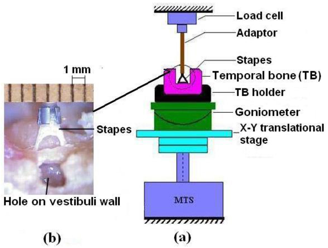
FIGURE 1.
(a) Schematic of the experiment setup for SAL test in MTS. The stapes head was fixed to the mounting fixture and the oval window bony wall with temporal bone was fixed on the rotational and translational stations. (b) A picture of the SAL specimen with the stapes and temporal bone structure taken during the experiment. The ruler was attached to the metal cap or the fixture at the load cell side as a dimensional reference.

