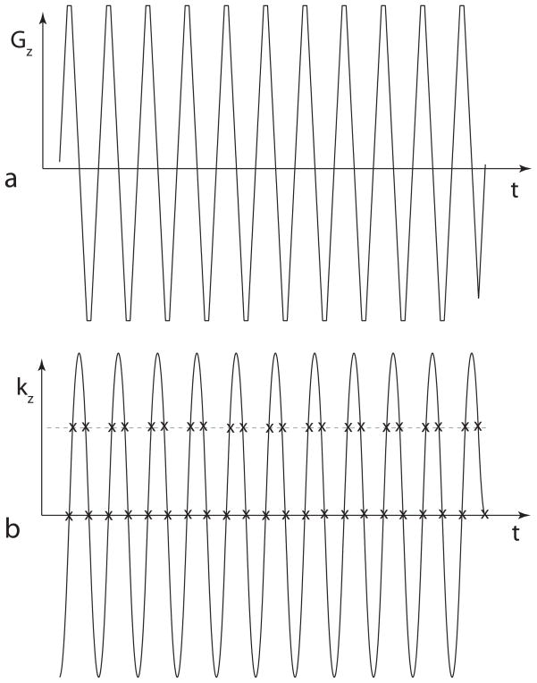
Figure 1.
The zig-zag trajectory through excitation k-space. (a) A gradient waveform used with a typical spectral-spatial RF pulse. (b) The integral of the gradient shape gives the trajectory through excitation k-space. The “x” marks show that the sample spacing across the central region is uniform, but is staggered away from the center. Compensating for this staggered sampling is the key to the design technique used in this paper.

