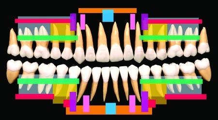
Figure 25.
Synopsis of placement sites for specialized (“second generation”) MMF screws as described in the text and listed in Table 2. The MMF screw insertion sites of the different study groups are superimposed symmetrically on a panoramic display of the upper and lower quadrants. For improved visualization the exit zones of the mental nerve and its branches around the foramen are not spaced in the scheme. (Color-coded fields—authors: Blue—Otten 19818; Pink—Schneider et al,45 Imazawa et al53; Magenta—Ho et al50; Blue and red—Hoffmann et al13; Blue and yellow—Maurer et al52; Green—Karlis and Glickman42; Yellow—Roccia et al19; Gray—Fabbroni et al22; Orange and gray—Coletti et al46)

