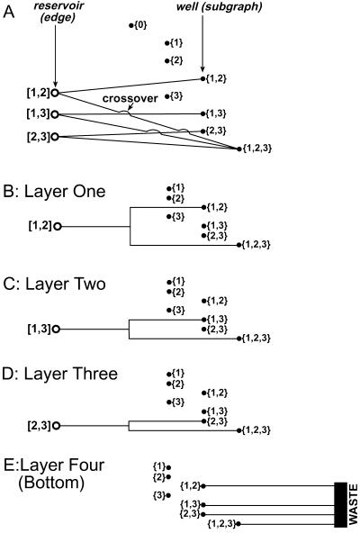
Figure 2.
(A) A schematic diagram that shows the encoding of a generic three-vertex graph as a set of reservoirs, wells, and channels. Reservoir [i,j] represents the edge that connects the ith vertex to the jth vertex. Each well represents a possible subgraph, and each edge [i,j] (reservoir) is connected by a channel to each subgraph (well) that contains {i,j}. To implement this representation in a microfluidic system, we must avoid crossover between the channels, which is accomplished by dividing the microfluidic network into layers (B–E): one layer represents one edge and all subgraphs that contain that edge. For example, Layer One (B) contains the reservoir for the edge [1,2] and the channels connecting it to wells (subgraphs) {1,2} and {1,2,3}, whereas Layer Two (C) and Layer Three (D) contain channels connecting reservoirs (edges) [1,3] and [2,3] to their respective wells (subgraphs). The Bottom Layer collects the fluids from the top three layers into a waste reservoir. Note that the sets {1}, {2}, and {3} do not contain edges, and so do not receive input from any reservoirs; we have omitted the empty set {0} in this figure.

