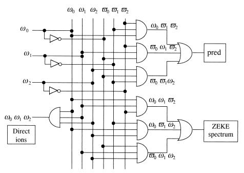
Figure 7.
The logic circuit corresponding to the full adder of Fig. 6. Three NOT gates, shown as triangles, are used to generate the logical complement (indicated by a bar) of the three Boolean variables (e.g., if the second laser is on, ω2 = 1 whereas ω̄2 = 0). Two OR gates, shown as a quarter-moon, are used to collect output. The vertical and horizontal lines are drawn to show which of the six variables (three ω variables and their complements) are the actual inputs to any particular gate.

