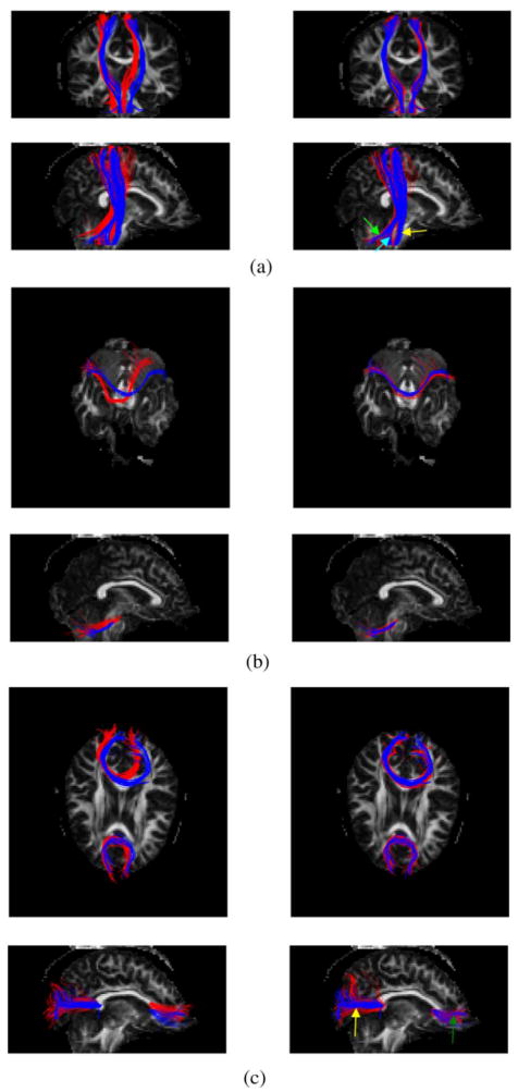
Fig. 3.

Superimposition of the template (red) and target fiber (blue) bundles on the FA map of the target data. The left column displays the unregistered template bundles with the target bundles, and the right column shows the registered and warped template bundles with the same target bundles. (a) CST (yellow arrow), ML (cyan arrow), and SCP (green arrow) bundles in coronal (top row) and sagittal (bottom row) views. (b) MCP bundle in transverse (top row) and sagittal (bottom row) views. (c) SCC (yellow arrow) and GCC (green arrow) bundles in transverse (top row) and sagittal (bottom row) views.
