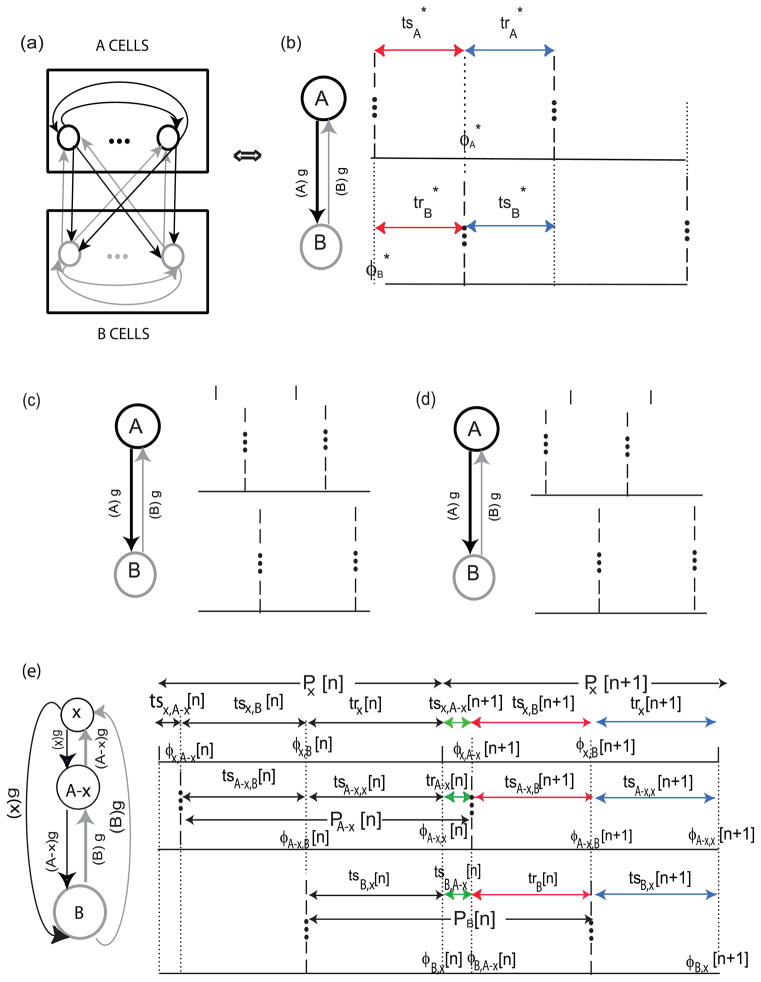
Fig. 2.
Two Cluster Mode Firing Pattern. (a) All to all circuit with identical coupling strength g. Each neuron within cluster A synapses (black arrows) on every other neuron in cluster A as well as on each neuron in cluster B. Similarly, each neuron within cluster B synapses (grey arrows) on every other neuron in cluster B as well as on each neuron in cluster A. The dots represent an unspecified number of additional neurons in each cluster. (b) Unperturbed firing pattern. In order to find the fixed point ), each cluster is considered as a single oscillator receiving a single synchronous synaptic input whose conductance strength g is scaled by the number of neurons in the other cluster: (A)g or (B)g. The stimulus (ts) and recovery (tr) intervals indicated in the same color (red or blue) are equal by definition. (c,d) Perturbation of the Firing Pattern. A group of neurons in cluster A is presumed to be slightly advanced (c) or slightly delayed (d) from the firing of the rest of cluster A − x. (e) A map of the perturbed firing pattern, with the perturbed sub-cluster x considered as a separate oscillator. There are nine named intervals on each cycle and six phases at which inputs are received on each perturbed cycle φij[n] (shown as dashed vertical lines) which denotes the phase at which neuron or cluster i receives input from neuron or cluster j. The three different colors (red, green or blue) indicate the equivalency of each set of intervals. These are used to reduce the complexity of the map as described in the text.

