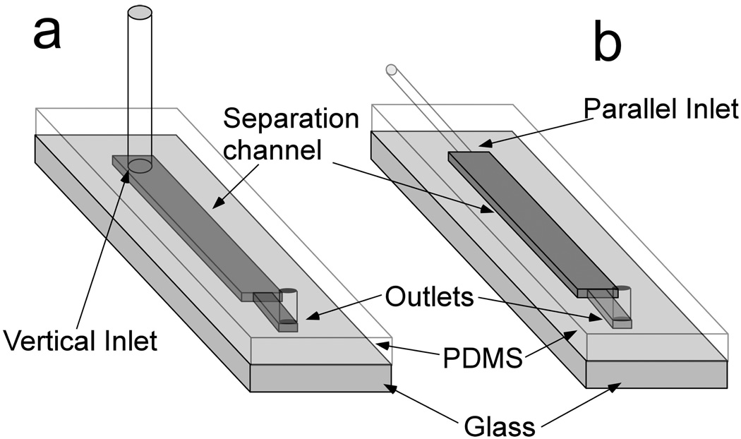
Fig.1.
Schematic of microfluidic device a) Vertical inlet chip. Holes were punched from PDMS slab to form the inlet and outlet. 30-guage PTFE tubing was connected to the inlet hole to load buffer and cell sample into the separation channel. b) Parallel inlet chip. Capillary (O.D. =360 µm) was inserted into the separation channel to form parallel inlet (See Supporting Information for fabrication procedure). 30-guage PTFE tubing was then connected to the capillary to introduce the cell sample to the separation channel. Both devices were fabricated following standard soft lithography protocols. Separation channel dimensions are 40 µm × 1 mm × 3 cm (height × width × length). The channel is narrower near the outlet (300 µm in width).

