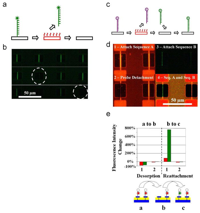
Figure 5.
Localized decomposition of immobilized molecules, and subsequent refunctionalization of the surfaces. a, Schematic summarizing the procedure for the heat mediated localized decomposition of the molecular layer. Device is represented with a black rectangle, and red indicates voltage applied to the device. After the immobilization of the appropriate functional layer on surface, the desired surface is heated by the application of voltage for the decomposition of the molecule. b, Fluorescent images showing the electrically addressable decomposition of the functional layer. The top image is taken before the experiment. Consecutive images (middle and bottom) are taken after heating the device encircled with dashed white lines. c, Similar to part a, but summarizing the procedure for the heat mediated localized functionalization of a device. A device can be re-functionalized with a desired probe after the desorption of the previous molecule. d, Fluorescent images summarizing the selective functionalization procedure. Initially a fluorescently tagged (HEX Sequence A) is immobilized on all the devices (1). The immobilized probe is desorbed by heating the left device (2). After this step, the chip undergoes the immobilization procedure for a distinct probe molecule containing fluorescently modified Sequence B (3). The last image in the series was obtained using a triple filter spanning both wavelengths for the imaging of the fluorophores simultaneously, and demonstrates the final patterning of two distinct probe molecules on adjacent devices separated by 50 μm (4). e, Percent fluorescence intensity change using both the TRITC (red bars) and FITC (green bars) filters during each of the steps displayed in part d.

