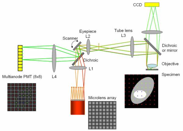
Fig. 5.
A schematic of the multifocal multiphoton microscope based on a MAPMT. Excitation beams are depicted in red/orange colors and emission beams are in green color. In this figure, only two beam-lets are ray-traced. The excitation beam is splitted into 8 × 8 beam-lets via a microlens array. Multiple excitation foci (8 × 8) scan the specimen. The emission beam-lets are collected either by a CCD camera or a MAPMT which has 8 × 8 pixels. L1, L2, and L3 are lenses. The transmission of light through the microlens array and high NA objective causes appreciable pulse dispersion which can be corrected by pre-chirping using a pair of prisms (not shown).

