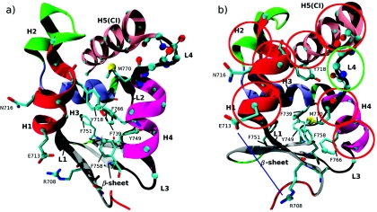
Figure 1.
VI converter in the R (a) and PPS (b) conformation. The secondary structure elements are helices 1–5 (H1–H5), loops 1–4 (L1–L4), and the β-sheet. We alternatively refer to H5 as the converter insert (CI) to emphasize that it is known to be present only in MVI (Ref. 53). The helices and loops are numbered in the order of increasing residue numbering. Atoms to which forces were applied in the RTMD or string simulations (see Tables 1, 2) are drawn as spheres. If forces were applied to a sidechain atom, the entire corresponding residue is shown. Atoms that are used to define the collective variables set CVS1 (Table 2) are shown as spheres. In (b), red circles are drawn approximately around subdomains that correspond to CV 1–21 in CVS2 (Table 3). The green oval is drawn around L4 and corresponds to the collective variables 46–50 in CVS2. The blue line corresponds to the distance CV 51 in CVS2.

