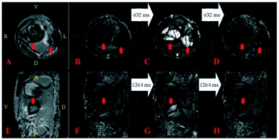
Figure 3.
Images of a 13-day old Manduca sexta, pupa. The orientation of the PDW and their corresponding FISP images is identical, so the orientation is only displayed on the former. For the PDW images: A = Anterior, D = Dorsal, L = Left, P = Posterior, R = Right, V = Ventral. The white arrows connecting the FISP images indicate the time that elapsed between the displayed images. A) Axial PDW image. The red arrows point towards the location of the air sacs. The slice location of A—D was 8.5 mm below the end of the proboscis. B—D) Individual frames from Movie 3 at the same location and orientation as (A); the frames were acquired 632 ms apart. The red arrows in the images identify the location of the air sacs. The intensity in (C) suggests the air sacs compressed. E) Sagittal PDW image. The red arrow identifies part of an air sac. The slice location of E—H was 1mm to the left of the end of the proboscis and the anterior boundary is 2mm above it. F—H) Individual frames from Movie 4 at the same location and orientation as (E); the frames were acquired 1264 ms apart. The red arrow in the images identifies the air sac and the hemolymph that occupies the same volume temporarily (G). See also Movie 3 and Movie 4.
Movie 3. Each frame is separated by 316 ms. Movie 3 corresponds to Figure 3A-D. See Figure 3A for orientation and structural information and the text for a detailed description. Two cycles of compression and inflation of the air sacs are seen about halfway through the movie. This video clip can be accessed at http://digital.library.wisc.edu/1793/23225
Movie 4. Each frame is separated by 316 ms. Movie 4 corresponds to Figure 3E—H. See Figure 3E for orientation and structural information and the text for a detailed description. Several cycles of compression and inflation of the air sacs as well as abdominal motion are seen during the first half of the movie. This video clip can be accessed at http://digital.library.wisc.edu/1793/23224

