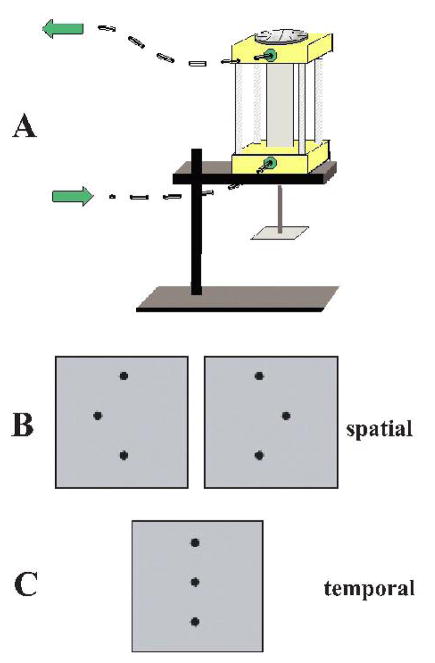
Figure 1.
A. MRI-compatible pneumatic stimulator. Stimuli were mounted face-down on the square base-plate at the bottom of the drive shaft. The finger mold used to immobilize the finger was mounted on the base of the device. Arrows indicate direction of airflow. B: Stimulus configurations in spatial task; central dot in array was offset either to the right or left. C: Stimulus array for the temporal task used an array without spatial offset. (Reproduced, with permission, from Stilla et al., 2007).

